Quadcopters are relatively easy to assemble but it took me the better part of a month to assemble Quadcopter 1 – my first quadcopter.
Figure 1 below shows the components of Quadcopter 1 and their connections to each other. In the following sections we explain how each sub-system is assembled.
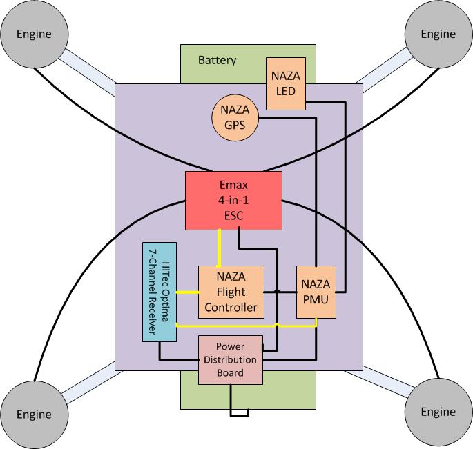
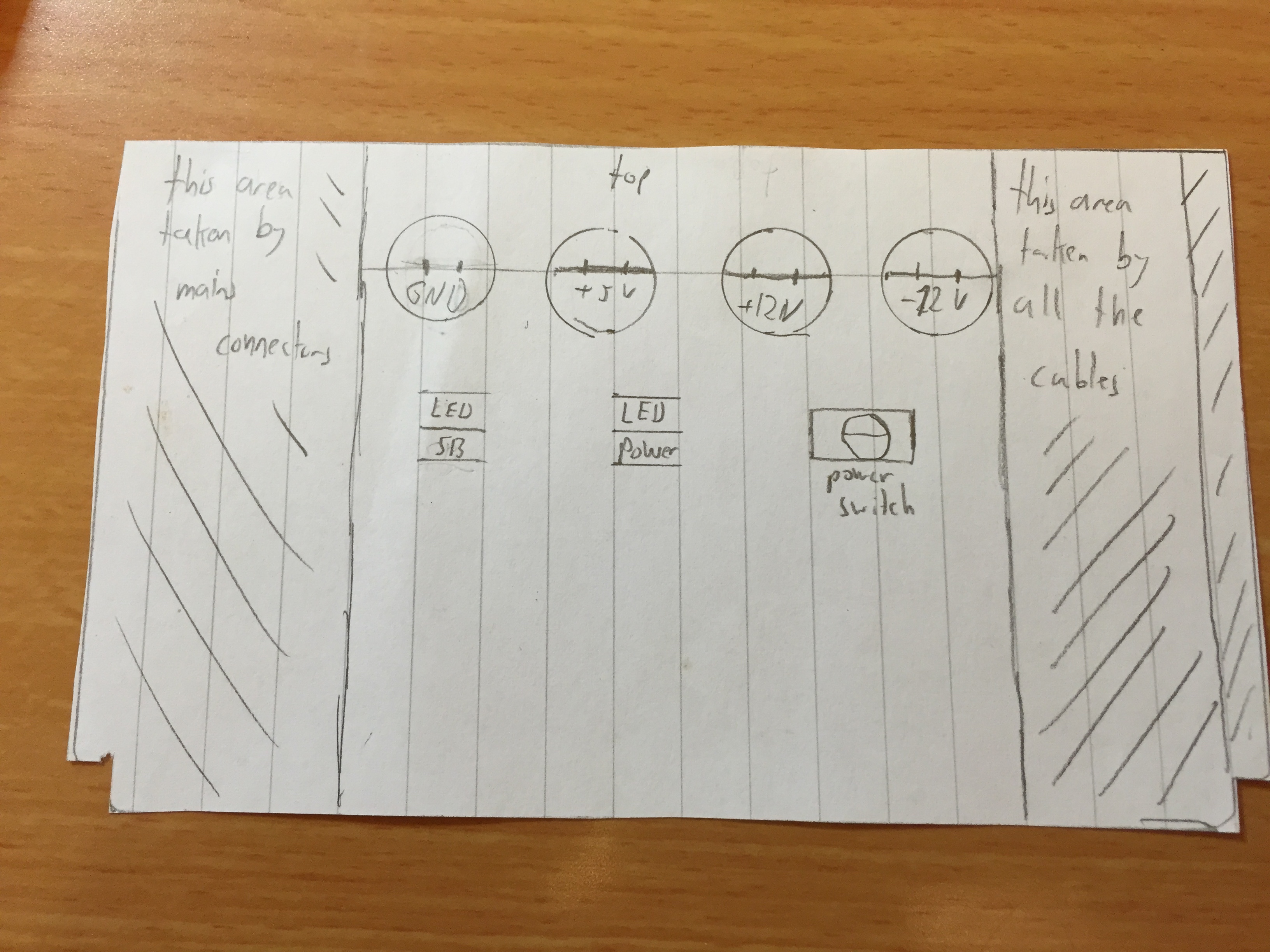
Figure 1: Quadcopter 1 schematic diagram
The black lines in figure 1 show the power connections and the yellow lines show the control connections.
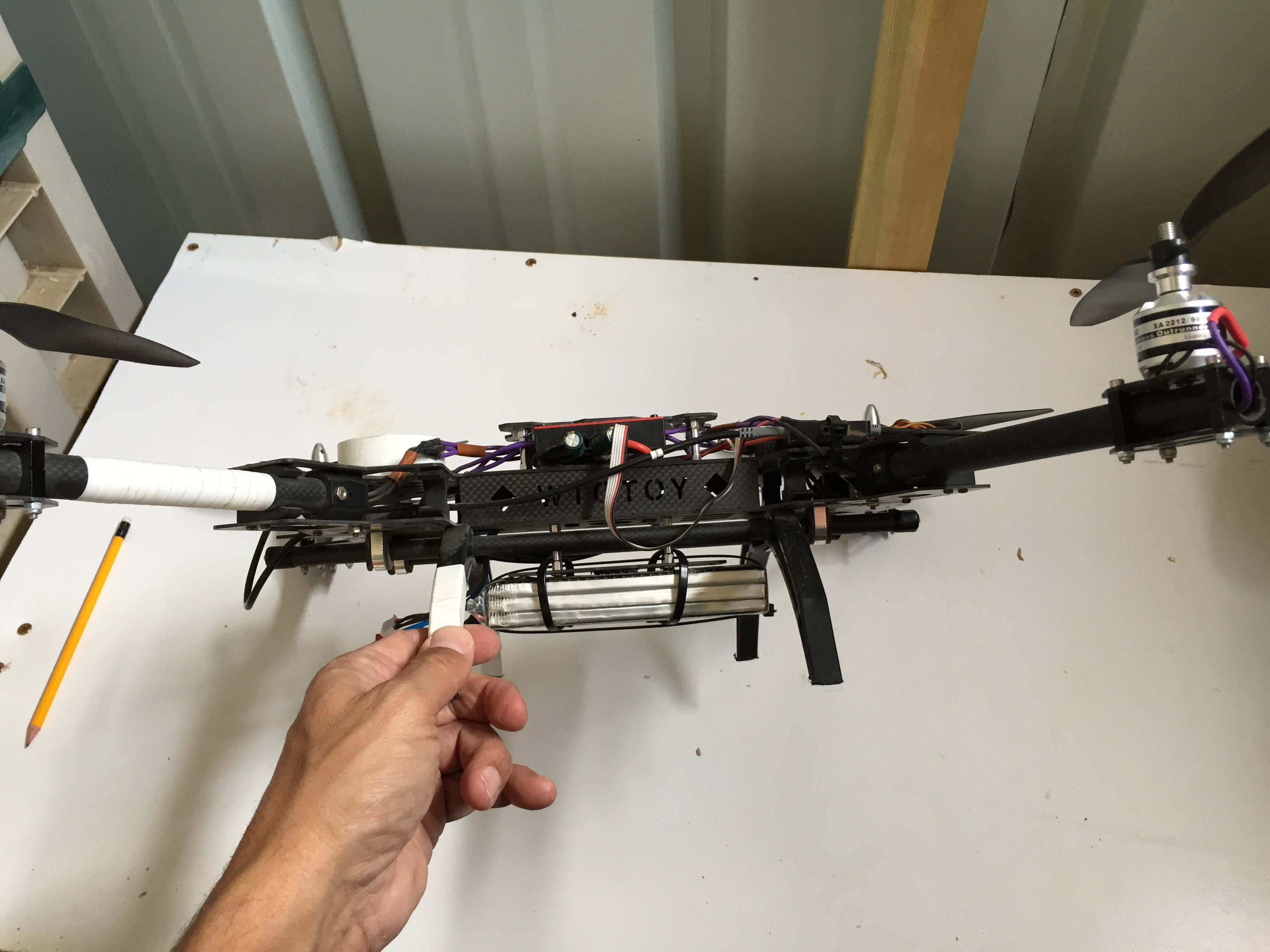
Figure 2 shows the assembled quadcopter.

Figure 2: Quadcopter 1 – assembled
Frame assembly
The frame arrived as a set of flat carbon fibre pieces and a small bag of screws and spacers. I had to study carefully the photos of the assembled frame on eBay in order to understand how to assemble it. Here is one photo for example.

Figure 3: Zoom in on the top and front part of the frame
I used 2 mm and 2.5 mm hex screw drivers.

Figure 4: Hex screwdrivers
Battery and the power distribution board
I decided to connect the battery with cable ties to the bottom of the frame because I’m not planning to use quadcopter 1 for photography and I will not connect a camera at the bottom.

Figure 4: Battery connection
After some trial and error I decided to use a double-sided PCB for the power distribution board. I soldered two 1.5 mm cables to both sides of the PCB and the two other ends to a Deans plug.
Note that the the power cables must be thick enough to allow the high power consumption of the ESC. At first I soldered thin cables that overheated very quickly and started to melt the plastic cover of the Naza flight controller at the point where they touched it. I then replaced the thin cables with 1.5 mm cables.
Engines and the 4-in-1 ESC
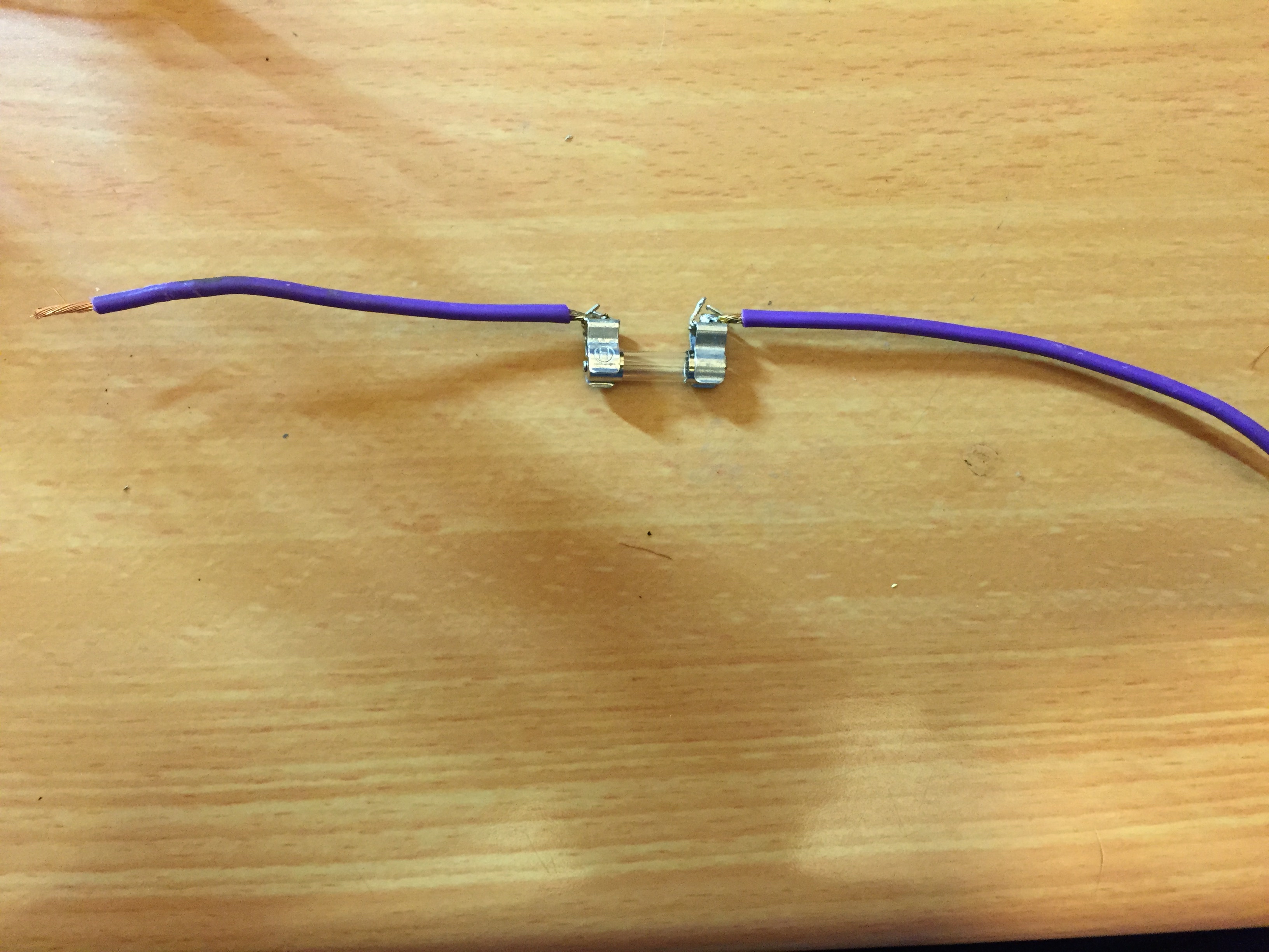
I soldered gold plated plugs to the three leads from each engine. I also soldered an extension of 1.5 mm cable to each of the cables that came with the 4-in-1 ESC because the original cables were too short for my large frame. I covered all the solder points with heat shrink tubing.
I passed the cables from each engine through the hollow engine arms.
The 4-in-1 ESC fits nicely on the center of the frame under a small cover that is screwed to four spacers. Figure 5 shows the ESC assembly.

Figure 5: ESC assembly
The ESC is held in place by velcro on it’s bottom and the cover piece with the text: “WTOTOY”
Naza components
The Naza system consists of the following components:
- Flight controller
- GPS
- Power management unit (PMU) – distributes power to the components of the system.
- LED module – indicates the system status and connects the controller to a PC for configuration.
I followed the assembly instructions in the Naza-M Quick start manual but I made a few changes in the location of the components as follows:
- The flight controller is not exactly at the centre of gravity (CG) of the vehicle. It is located astern of the ship (on the back).
- The GPS is also not at the center of gravity but on the bow (forward) of the airship. In the beginning I used the pole that came with the package and glued the GPS case (the white plastic protector around the GPS unit) to it right at the CG. However, after the first few crashes I realized it will be much safer if I attach it to the frame itself.
At first I connected the flight controller and the GPS with velcro strips but then I realised (I realised many things during the process 🙂 ) that the velcro allows the flight controller to move and shake a bit and this is certainly not good. Therefore I replaced the velcro with double sided glue strips similar to these – some were provided by DJI in the Naza package but I bought a few more myself.

50Pcs Double-Sided Adhesive 3M PE foam Sticker Size 25MMx40MM For RC Model Gyro
This glue is very strong after it bonds, but it is always possible to pry it off with a knife.
The receiver
I attached the Hitec Optima receiver with velcro strips to the back side of the frame near the flight controller. The choice of location was mainly because of the short servo cables that I had for connecting the Naza to the receiver. A side advantage is that it is also protected by the strong carbon fibre frame.

Figure 6: The Optima receiver
Landing gear
The landing gear that came with the frame has very long plastic “legs”. It looked really good when it stood on these legs on my desk but they were too elastic, so often when the ship landed not completely softly it would bounce up and land on its back or side. This went on for quite a long time and through many crashes.
Luckily, if I may say so, I once completely lost control over the quadcopter and turned on the RTH (return to home) feature. When a Naza goes into RTH mode it first climbs to a height of 20 meters and then heads home. On that particular occasion the winds were very strong and the screws holding one of the engine to the frame became loose during all the crashes. So suddenly the engine broke loose and the ship crashed from 20 meters to the ground. Amazingly, all the carbon fiber parts were almost not damaged but one of the plastic legs broke. I didn’t have a replacement so I decided to cut the other three legs to the same length and suddenly I realised that this is perfect. The short legs are not elastic any more and when the craft lands it sets squarely on its legs and doesn’t bounce at all.
So I definitely recommend using a non-elastic landing gear. I am not planning to install a camera under the frame so I am not going to replace the legs that I have even though they are quite short.
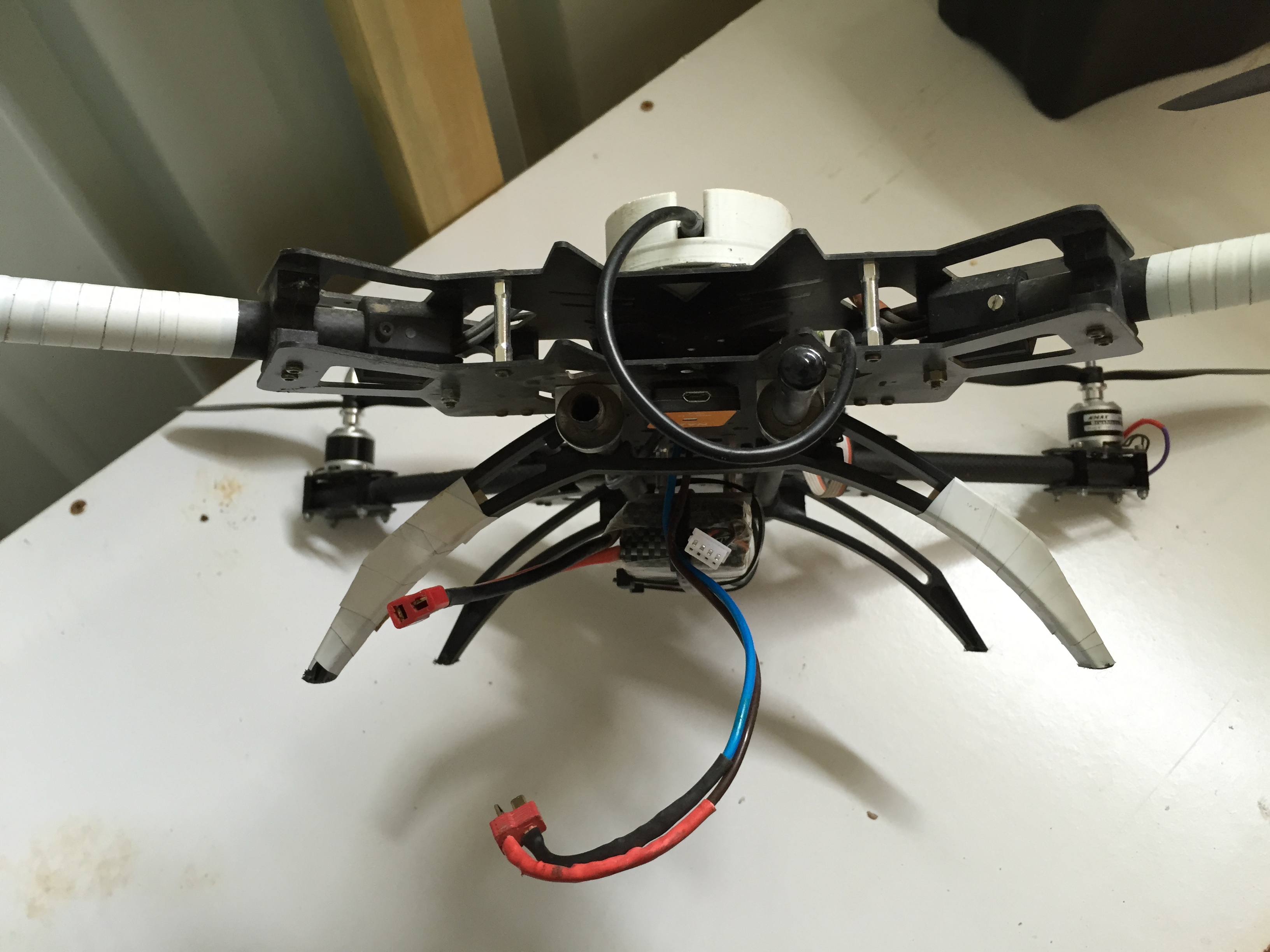
Marking the “front”
In the basic flight mode the operator must be aware which side of the quadcopter is the front. Therefore I marked the front of the vehicle (the front legs and the front engine arms) with white tape as can be seen in the next photo.

Figure 7: Marking the front of the quadcopter
Propellors
The propellors must be installed at the very last step of preparing the quad copters for its first flight. So I will describe the propellor installation in the next post on “Preparing to fly”.