The last step of preparation for some serious PIC programming is to learn how to use the serial interface of the PIC for reading (Rx) and writing (Tx). So I decided to enhance the 3-Digit 7-segment display to read the input value over the serial connection. To test it I wrote a simple serial transmitter that sends the numbers from 1 to 255 first counting upwards (1 to 255) and then downwards (255 to 1) over and over again. The 3-digit display shows these numbers that it reads from its serial port.
The transmitter
First some definitions for the direction of counting
#define UP 1 #define DOWN 2
Then the timer 0 counter
int timer0count;
The ISR simply increments the timer 0 counter every time Timer0 rolls over
Clearing the analog output bit for pin A0 that we will use for Tx
// The analog bit must be cleared for RX to function ANSELAbits.ANSA0 = 0;
timer0count = 0;
Enabling the interrupts – needed for Timer 0
INTCON = 0xC0 | 0xE0; INTCONbits.GIE = 1;
while(1) {
We wait for 2000 overruns for transmitting a number. This comes out around 16 times a second. if (timer0count < 2000) continue;
timer0count = 0;
The TRMT bit indicates whether we can write a character to the transmit register. We can write if it is set. if (TRMT == 0) continue;
Transmitting a character is done by writing it to TXREG
TXREG = value;
Then we increase of decrease the value. if (direction == UP) value += 1; else value -= 1; if (value == 254) direction = DOWN; if (value == 1) direction = UP; } }
The receiver
We will not copy the 3-digit controller again, but only point out the differences.
First the updated ISR with the new section highlighted in bold. The new section reads a character from RCREG when the RCIF flag is raised.
void interrupt ISR() { if (INTCONbits.TMR0IF) { timer0count++; INTCONbits.TMR0IF = 0; TMR0 = 0; } if (PIR1bits.RCIF == 1) { if (FERR == 0) adcvalue = RCREG; if (OERR == 1) { overrun = 1; } } }
Next is a new function to indicate that there is an overrun error. An overrun error occurs when a character is received before all the characters have been read from the 2 character input buffer. I decided to indicate this condition by lighting one segment on each digit. This is done by the following function:
// The analog bit must be cleared for RX to function ANSELAbits.ANSA1 = 0;
The last change is in the switch statement that shows the digit. Here we check for an overrun and display the overrun error or the digit:
if (overrun == 1) show_overrun_error(); else show_number(digits[digit1index]);
Demo
This is how it work. The 3-digit controller is not perfect yet and the digit (especially to left most one) are flickering. But it does show the numbers correctly and will be very helpful in debugging my applications.
I’m publishing this post a bit out of order as I already published the post about flying because it was simpler and shorter. However, lets not get hung up on small details. So here I explain the last stages of preparation before flying.
The stages are:
Pair the receiver to the transmitter
ESC calibration
Naza calibration
Attach the propellors – they must be completely parallel to the ground
Hold it by hand to see that it responds correctly to RC commands (if it is a small model). Alternatively, you can ask someone to help as I’ll explain.
Find an empty field large enough to fly without crashing into something, or worse, some spectators
All the steps from 1 to 5 should be carried out with the propellors NOT attached to the engines.
Pairing the receiver to the transmitter
Usually most transmitters and receivers have buttons that place them in pairing mode. Follow the procedure for your devices. I found that my Hitec transmitter works with the Hitec Optima receiver (obviously) and with the cheap Minima receiver.
ESC Calibration
The purpose of ESC calibration is to set the throttle range onto the ESCs. Follow these steps to do that:
Connect the signal cable of the ESC (its color is usually white) to the throttle channel of the receiver. This is usually channel 3 and the signal connector is the upper one.
Turn the transmitter on
Push the throttle to the top most position
Connect the quadcopter power. The receiver should come on
The engine should beep twice
Within 2 seconds move the throttle to the bottom position
The engine should beep 3 times and the ESC should reset itself
Move the throttle up and verify the engine starts. Note the direction in which the engine rotates – clockwise (CW) or counter clockwise (CCW)
The ESC programming instructions are usually the same for all ESCs because they all run the same SimonK firmware. The instructions for my 4-in-1 ESC can be found here.
Note that when the engine starts it should beep several times corresponding to the number of cells in the battery. If one or more engines beep a wrong count then these engines should be programmed. The programming instructions can be found in the ESC manual.
After all engines are calibrated connect the ESC signal cables to the correct engine ports on the Naza controller.
Naza calibration
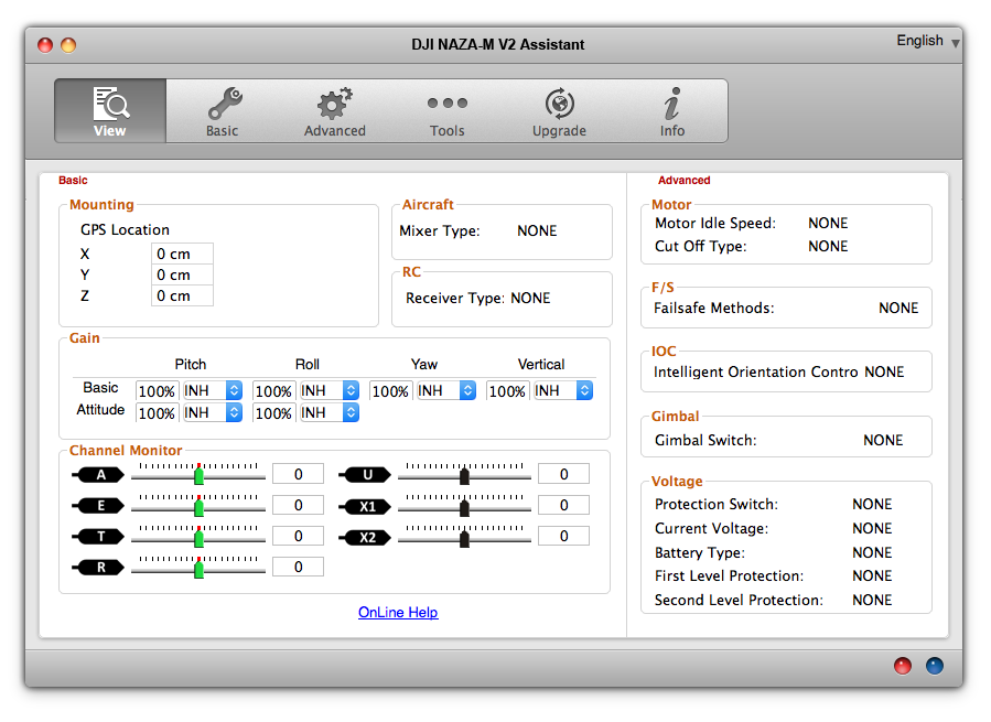
Naza calibration is guided by the Naza configuration application DJI Naza-M V2 Assistant that runs on Windows and MAC. Here is a screenshot of it’s first screen.
I will not repeat here the information and instructions listed in the Naza-M quick start manual. I will only point out some important points that might be overlooked.
It is important to do all the configuration steps when calibrating the Naza for the first time especially the IMU calibration in the Tools window.
I recommend to do the Naza compass calibration as well. This procedure is described here.
Attaching the propellors
Note that there are two clockwise propellors (CW) and two counter-clockwise propelloers (CCW). The propellors must be attached so that the two CW and the two CCW propellors are at the edges of the diagonals.
You must also ensure that the engines rotate the right way, i.e. the CW propellor should rotate CW and the CCW propellor should rotate CCW. If an engine turns the wrong way then disconnect two of the engine’s three power cables and swap them, meaning that each should be connected to the other lead coming from the engine. This will reverse the engine’s direction.
Hold the quadcopter by hand and run a dry test
This is a risky step and I suggest to do it only if you are a cool headed grown up guy/girl and your model is small enough to hold it with one hand. If the model is large then you should ask someone to help and hold it above his head.
So, hold the quadcopter tightly, arm the system and bring the throttle up until all propellors spin. Be careful not to let go.
Now move the remote control sticks and verify that the quadcopter responds correctly.
Next release the sticks and let them return to their center position. Then hold the quadcopter and tilt it to each side. You should feel the quadcopter resist as it tries to stabilize itself.
Flying:
Before flying you should perform the following checklist:
All screws are tight. Especially those that connect the engines to the frame
The battery is attached securely
The propellors are screwed on tightly
The propellors are parallel to the ground
The indicator lights are in their normal state
First flights
My first flights were catastrophic. I crashed the quadcopter many times and broke many propellors and some engines. So here are some tips to get you started:
Be patient – its takes time for your fingers to learn the controls and respond quickly and correctly.
Start flying in normal mode – be aware where the “forward” direction is and stand behind the quadcopter.
Start with simple flights – lift of and land, lift off, move one meter to each direction and land. And so on …
Don’t start flying in strong winds.
Try to fly the quadcopter circles. I think that if you succeed (in normal flight mode) then you are doing nice progress.
The LED Controller (LC) for quadcopters controls up to 4 high-power LEDs that can be attached to the quadcopter and can be used to make it visible in the dark and/or indicate the status and condition of the quadcopter.
The LC supports multiple configurations of LEDs as described below. It allows the operator to select configurations via the remote control over a dedicated channel.
The blinking interval (the length of time that the LEDs are on or off) can be set by a potentiometer.
The LC may include an optional 7-segment display that shows the LC state.
Hardware
The LC consists of the following HW components:
Component
Purpose
PIC16F1825
Application processor – runs the main LC application
PIC16F1826
Optional 7-segment display controller
7-segment display
Optional. Displays:
the blink interval
the PWM min and max values while in settings mode
the configuration number (see below) while the user is changing the mode
10K Potentiometer
Defines the “blink interval” the amount of time a LED stays on when blinking
Push button – SPST
Forces the LC into settings mode
4 Transistors
For switching current to the LEDs. One for each LED.
4 High power LEDs
LED Configurations
The LC supports the following configurations:
ID
Name
Description
1
All off
All LEDs are off
2
All on
All LEDs stay on permanently
3
All blinking – 1 – High intensity
All LEDs blinking in a fixed rate – on and off
4
All blinking – 1 – Low intensity
All LEDs blinking in a fixed rate – on and off
5
All blinking – 2 – High intensity
All LEDs blinking twice and then a break
6
All blinking – 2 – Low intensity
All LEDs blinking twice and then a break
7
All blinking – 3 – High intensity
All LEDs blinking three times and then a break
8
All blinking – 3 – Low intensity
All LEDs blinking three times and then a break
9
LEDS 1, 2 on and 3, 4 off
10
LEDs 3, 4 on and 1, 2 off
11
LEDs 1, 2 blinking 1 – High intensity
LEDs 3, 4 are off. LEDs 1 and 2 are blinking in a fixed rate
12
LEDs 1, 2 blinking 1 – Low intensity
LEDs 3, 4 are off. LEDs 1 and 2 are blinking in a fixed rate
13
LEDs 1, 2 blinking 2 – High intensity
LEDs 3, 4 are off. LEDs 1 and 2 are blinking twice and then a break
14
LEDs 1, 2 blinking 2 – Low intensity
LEDs 3, 4 are off. LEDs 1 and 2 are blinking twice and then a break
15
LEDs 1, 2 blinking 3 – High intensity
LEDs 3, 4 are off. LEDs 1 and 2 are blinking three times and then a break
16
LEDs 1, 2 blinking 3 – Low intensity
LEDs 3, 4 are off. LEDs 1 and 2 are blinking three times and then a break
17
LEDs 3, 4 blinking – 1 – High intensity
LEDs 1, 2 are off. LEDs 3 and 4 are blinking at a fixed rate
18
LEDs 3, 4 blinking – 1 – Low intensity
LEDs 1, 2 are off. LEDs 3 and 4 are blinking at a fixed rate
19
LEDs 3, 4 blinking – 2 – High intensity
LEDs 1, 2 are off. LEDs 3 and 4 are blinking twice and then a break
20
LEDs 3, 4 blinking – 2 – Low intensity
LEDs 1, 2 are off. LEDs 3 and 4 are blinking twice and then a break
21
LEDs 3, 4 blinking – 3 – High intensity
LEDs 1, 2 are off. LEDs 3 and 4 are blinking three times and then a break
22
LEDs 3, 4 blinking – 3 – Low intensity
LEDs 1, 2 are off. LEDs 3 and 4 are blinking three times and then a break.
Main use cases
The main use cases of the system are:
1. Initialization
When the LC starts it enters the initialization sequence. The init sequence is described in a separate post.
2. Normal operation
In normal operation the LC drives the LEDs according to the currently selected configuration. The LC also monitors the following inputs:
a. Potentiometer – the potentiometer value determines the blink interval – the time that LEDs, in blinking mode, are on and off. In the “blinking 2” and “blinking 3” modes, the potentiometer value determines also the amount of time that the LED is off between blinks. This amount of time is twice as long as the blinking interval. When the value of the potentiometer changes the LC performs the “Setting the blink interval” use case.
b. RC input. If the PWM value on the RC channel changes then the LC performs the “Changing the LED configuration” use case.
During normal operation the 7-segment display, if present, shows the ID of the current LED configuration.
3. Setting the blink interval
When the blink interval is changed (i.e. the potentiometer value is changed) and if the 7-segment display is present, then the LC displays the new value of the potentiometer for 1 second. After 1 second the display returns to showing the configuration ID.
4. Changing the LED configuration
When the PWM value changes, the LC moves to the newly selected LED configuration. The LC also displays the current configuration ID on the 7-segment display, if present.
The LED controller for my quadcopter will be controlled by by the remote control on one of the PWM channels. The last step of preparation before writing the LED controller itself is to understand how to listen on a remote control (RC) channel and detect the PWM “value” that is transmitted on the channel.
I decided to connect my cheap Minima receiver to the circuit and write a small program to display the PWM value, that I’lll transmit to it, on my 3-digit, 7-segment display. The Minima is sold by Hobbyking.com here. It is compatible with my Hitec transmitter and the price is just 19.73 euros, which is cheap compared to the original Hitec Optima receiver.
I had to come up with a method for communicating between the two PIC16F1825 controllers because the application controller has to transmit the PWM value to the 7-segment controller. I thought of using the USART serial interface but I decided to use the DAC (Digital to Analog Conversion) feature of the PIC16F1825. In this mode, the chip can output 32 voltage levels on pin RA0 – the DACOUT pin. This pin is connected to input pin RA2 on the 7-segment controller. The 7-segment controller displays a number between 0 and 99 that corresponds to the voltage on its input pin so it will display a number that corresponds to the PWM value. I decided to use this method because accuracy is not important in this project.
Set up
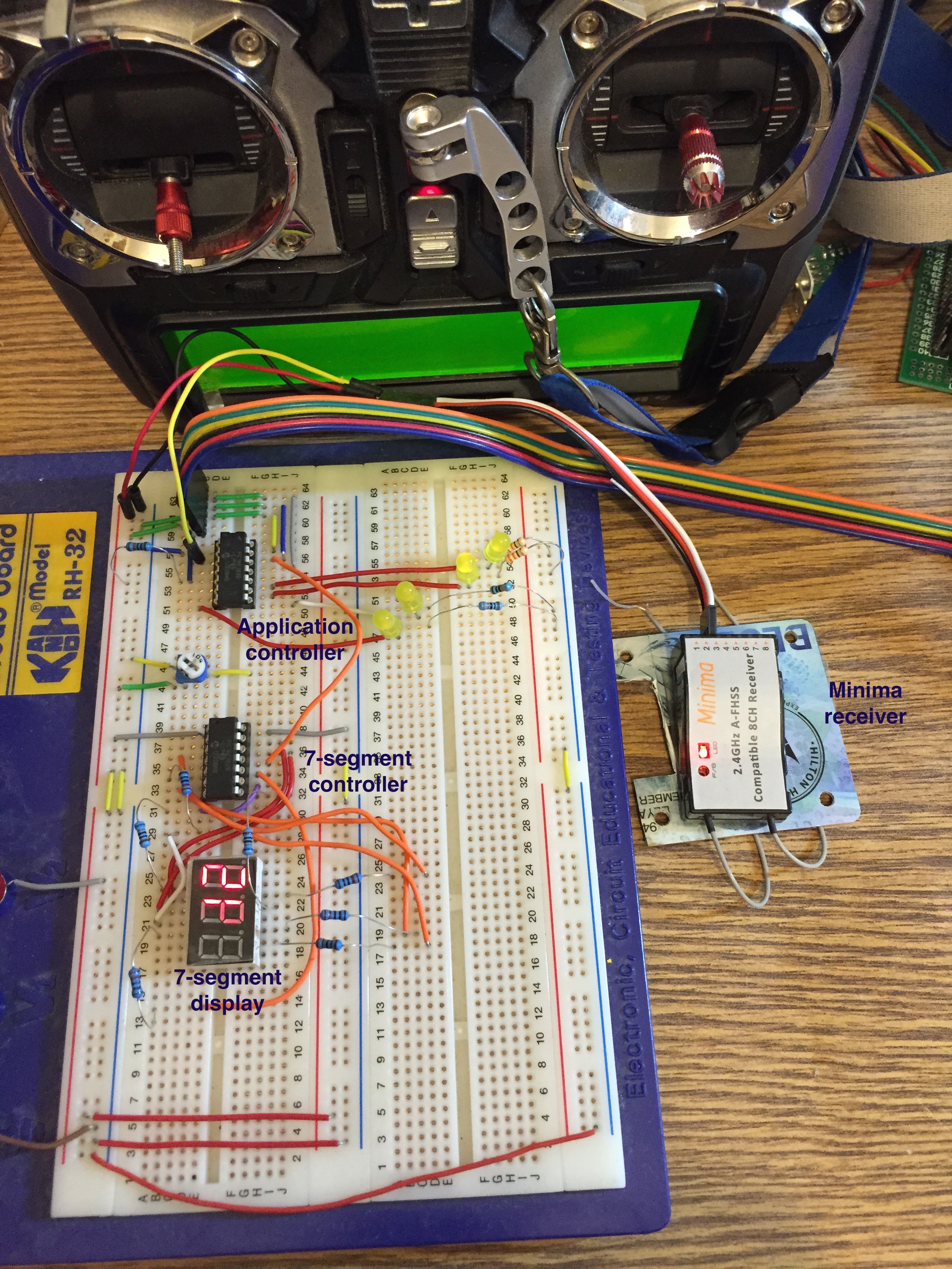
The circuit is shown in the picture below.
The RC transmitter at the top is my Hitec Aurora 9. On the right side, outside the breadboard is the Minina receiver. Its red LED is on indicating that it is connected to the transmitter. The receiver is connected with 3 cables from its channel 3 output to the breadboard:
Red cable connected to +5V
Black cable connected to GND
White/Yellow cable – the signal cable (white on the Minima side and yellow on the breadboard side) connected to pin RA5 of the application controller.
There are 2 PIC16F1825 controllers on the board:
Application controller (top) – runs the PWM capture function
7-Segment controller (bottom) – drives the 7-segment display.
Application controller
The application controller is connected to 4 LEDs that are not part of this project. They are there because I don’t want to take them out for every picture that I take of the breadboard and eventually they will be part of the LED controller.
The application controller is also connected to the PICKit3 data cable that connects to RA0, RA1, RA3 as I described in a previous post.
The two connections relevant to this project are RA5 – the PWM input, and RA0 – the output of the analog signal to the 7-Segment controller. RA0 functions as the DACOUT pin (Digital to Analog Converter Out).
7-Segment controller
The 7-segment controller is described in a previous post. It receives an input voltage, between 0V and +5V) on pin RA2 and displays a number between 0 and 99 that corresponds to the input. The input pin, RA2 is connected to the DACOUT pin on the application controller (RA0).
Code
The code is quite simple. I use the IOC (interrupt on change) feature that calls the ISR whenever a rising or falling edge is detected on an input pin. I also use Timer 1 to time the PWM duty cycle – the time the line is high.
The I use the DAC (digital to analog converter) to pass a value to the 7-segment display controller.
/* * File: main.c * Author: Eli Gurvitz – Quadcopter Blog * * Created on February 26, 2015, 10:59 PM */
#include <xc.h>
The rising and falling edge #defines are used in the ISR. The LOWPWM is the value of the lowest PWM reading. I found it by using the debugger.
The state variable indicates if we are dealing with a rising edge or a falling edge.
static int state = RISING_EDGE; unsigned int newvalue;
if (IOCAF5 == 1) {
If the ISR is called for a rising edge then we reset timer 1 and change the IOC setting to interrupt on a falling edge (the IOCAP and IOCAN registers).
If the ISR is called for a falling edge then we read the value of timer 1. If the value is different from the previous value then we update the PWM value. Then we set IOC to be called on a rising edge. newvalue = (TMR1H << 8) + TMR1L; if (newvalue != pwmvalue) { pwmvalue = newvalue; } state = RISING_EDGE; IOCAP5 = 1; IOCAN5 = 0; } IOCAF5 = 0; } }
/**************************************** * ****************************************/ void main() { int i; int j;
OSCCON = 0xF0; // set internal osc to 32Mhz
Timer1 settings
TMR1ON = 1; TMR1GE = 0;
Setting RA0 for output and RA5 for input.
TRISA0 = 0; TRISA5 = 1;
Setting the IOC for pin 5. The initial setting is for detecting a rising edge.
IOCAP5 = 1; IOCAN5 = 0; IOCAF5 = 0; IOCIE = 1;
GIE must be enabled in order to receive the IOC interrupts.
GIE = 1;
DAC settings – enable DAC and enable the DACOUT pin.
DACEN = 1; DACOE = 1;
Main loop – I decided to update the 7-segment display only periodically (on a count to 10000). This
while(1) { if (i > 10000) {
Initially, I tried to calculate the DACOUT value (which is set by writing to the 5 LSBits of DACCON1) by a simple function (see below) but it didn’t work. Therefore I compare the PWM value to each possible value from the lowest (LOWPWM) and up to 32 increments (of 200 in this case) and set DACOUT to the index of the increment. This is good enough for the purpose of this sample.
I tried using the PWM capture feature of the PIC16F1825 but it didn’t work. It never stopped in the ISR (Interrupt Service Routine).
At first I tried to calculate the output value in the following way but it never worked. The DACOUT value varied between 3 and 8 and never corresponded to the value of the function described below.
Divide the PWM input range into 32 groups. Each group has a size of (PWMHIGH – PWMLOW) / 32
Normalise the PWM input by subtracting the min value from it.
Divide the normalised PWM input by the group size.
Or, in other words: DACOUT = (pwmvalue – PWMLOW) / group size = (pwmvalue-PWMLOW) * 32 / (PWMHIGH – PWMLOW).
Quadcopter 1 is built with the Naza M V2 flight controller from DJI. It is expensive but worth every penny for the novice pilot because it is very stable and very easy to fly. it will give you the satisfaction that you need so much and the confidence that you can do anything with it. My good friend Misha started flying with an Arducopter controller and quickly gave up.
Here is a recent video (published with permission of the participants) of me flying it in a small parking lot just a meter away from the excited crowd (children are the best crowd for this kind of stuff).
However, I must confess that I do this after relatively many hours of flying the Naza and, I’m not exaggerating, tens of broken propellors, two damaged engines and a fractured carbon fibre frame. DON’T DO YOUR FIRST FLIGHT IN A SMALL PARKING LOT.
My first flight was catastrophic. I bought only 8 propellors and I attached four of them to the engines in a random way. I remembered Misha laughing about people who buy ready made coppers like the Phantom, who don’t even know which way the propellors are attached, but I didn’t understand what he means and I didn’t know what to ask. So I attached the propellors, took it to a large parking lot at night, armed the controller, moved the throttle up and the quadcopter flopped on its head breaking two propellors. I replaced the propellors and tried again, same result with one broken propellor. I took it home and started reading the configuration instructions carefully I soon understood how to attach the propellors correctly (see the “Preparing to fly” post).
The next day I went to the parking lot again, this time with the propellors attached correctly. I armed the controller, moved the throttle up and the copter lifted off the ground, took a wide angle and crashed into a lighting pole. Two propellors broken again and I couldn’t continue flying. I went home and ordered a large number of propellors (I think 20) from a supplier in China but I couldn’t just sit and wait a month for them to arrive. So I went the next day and bought 2 propellors from an importer in a nearby city for six times the chinese price.
After a few more careful flights I could lift it off the ground an land. I decided that I must now start practicing on moving it sideways a bit. So I went to a large field, lifted off and it started flying away, assisted by the strong winds (I live in a mountain region, 800 meters above sea level with strong winds). I couldn’t understand how to make it return to me, so I panicked and switched to the RTH (return to home) mode. In this mode the Naza copter first climbs up to 20 meters and then heads “home”. I saw it climbing up then starting to fight the winds in order to return to the home position, suddenly something snapped and the copter fell from 20 meters to the ground not far away.
I ran to the crash spot and was amazed to see that 3 propellors were broken, one engine shaft was bent but the carbon fibre frame was intact apart from a very small dent. Now I really had to wait a month for new engines to arrive. When I inspected the copter I found the reason for the crash – the screws attaching one engine to the frame came loose, and the engine snapped off. This is something you don’t want to happen in mid-air, especially since I’m writing this post in an airplane on the way to the London Heathrow airport. Not a bright thought at all.
I now had some time to think and I understood that I must perform all the calibration steps and, most importantly, make sure that the propellors (and engines) are completely horizontal. If they aren’t then the copter will rotate or simply fly away. It is easy to detect which engine is not horizontal – it will be hotter than the other engines.
The next time I flew it, it lifted off cleanly, kept its position and height and responded to commands beautifully. Here is a video from that period.
After some more practice I became so confident that I let friends fly it with no training at all. I would give them the transmitter, stand behind them while holding their fingers, and show them the basic movements. They could fly it very nicely just like that without any practice. I stopped doing that after someone panicked and turned off the engines in mid-air and someone else borrowed it for a few days and returned it with 2 broken propellors.
Here is a video (published with permission) of some 2-legged friends and 4-legged friends flying my Quadcopter 1.
So, the main point is that anyone can fly a Naza and I strongly recommend paying more for a Naza at least for the first quadcopter.
While working on the LED controller I decided that it would be nice if the blinking interval (the length of time a LED is on or off) will be controlled by a potentiometer. Then I remembered that I bought a few 3-digit 7-segment displays (see footnote) and it would be even nicer if I’ll show the pot setting on the display. It will add some color to the LED controller. I also bought some new PIC16F1825 controllers with 14 pins which are perfectly suited for the job. So I had everything ready and to my surprise it took me much longer to get it working than I anticipated.
I had to learn a few new things to make this work:
Using the ADC (Analog to digital feature of the PIC16F1826)
Connecting the display to power and to the controller
Driving the 7-segment display.
First of all, here is the final system. Notice how the numbers on the display change as I turn to pot with the screwdriver.
I’ll start by describing the wiring of the circuit.
Wiring
See Important update to the wiring scheme below
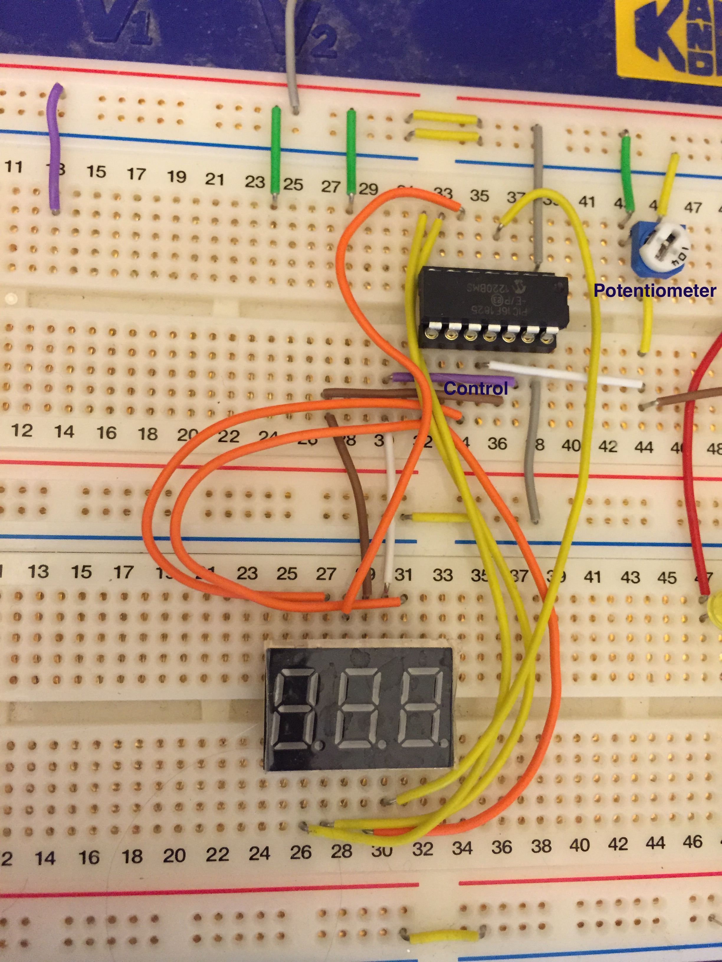
The image below shows the wiring of the potentiometer (marked), the PIC16F1825 controller and the display.
Wiring
The VDD and VSS pins are connected to the power via the two grey wires at the right side.
The two wires marked “control” – a purple one connected to RA0 and a brown one connected to RA1 – control which digit is “displayed”, or more correctly – powered up. This display is a common anode display. This means that all the segments of a digit are connected to a single positive pin. There are three such pins, one for each digit. In order to light up a segment, the digit’s control pin must be positive and the segment’s pin must be negative. In order to display two or three digits at the same time, the program must switch the control pins on and off rapidly. In this project I’m using only two digits – to display numbers in the range 0 – 99.
Pin RA2 is connected to the potentiometer.
The yellow and orange wires connect each of the 7 segments to a pin on the controller according to the table below. The table shows the assignment of the controller’s pins to segments (segments are marked by the letters A – G) and the segments that must be lit to display each digit. For example, to display the number one, segments B and C must be on. This table is actually good for a common cathode display – I made it before I realized that I have a common anode display. So you’ll see that in the code the bits are negated.
Pin RA4 is connected to segment G.
The problems
I had to take care of several issues in the code and I’ll explain how each one is handled. The main problems were:
The display is of the common anode type, meaning that to light a segment, its pin must be low (0)
The display has only 11 pins to control 3 digits, each with 8 segments (the 8th is the decimal dot). This means that the controller needs to turn them on and off in a round-robin way.
The pot is completely not stable – it sends different readings continuously. I had to “smooth” out the constantly changing readings
The initial, naive implementation was really dumb and had all the mistakes possible in such small program. When I ran it all the segments on both digits were flickering wildly and one of the digits was brighter than the other. The problems were:
I assumed that a positive voltage on a pin will light a segment but my display was of the common anode type, so a pin must actually be low to light a segment. The lighted segments didn’t resemble any number of course.
I understood that I have to switch each digit on and off, but the code first switched on digit 1, then switched it off and right after that, in the same function, switched digit 2 on and only after that changed the lit segments to show digit 2. This implementation really had all the possible errors and it caused one digit to be bright and the second to be dim.
I didn’t remember that the pot keeps sending different readings all the time, so the digits never stabilised (and of course, I couldn’t make out any digit because of the confusion with common anode vs. common cathode).
Solutions that didn’t work
I first thought that the controller can’t source enough current to light up the digits, so I connected the control pins to the 5V input via a transistor. This of course made no difference.
I realised that the pot is fluctuating wildly so I installed a low-pass filter – a resistor and capacitor in series. This was an interesting exercise and I played with various combinations of resistors and capacitors and watched the effects. This help a little but not much. I understood finally that a low pass filter is not a solution to the problem because even if it smooths out the input a little bit, some readings will pass through and make the display flicker.
So I started simplifying the circuit and the code and trying to isolate problems – first light up a single hard-coded digit, then two digits and then connect it to the pot.
Solutions that did help
I read the display’s data sheet to the end and found that the duty cycle of each digit is 1/10 and the actual time that it must be lit was 0.1 millisecond. So I understood that the correct way to drive the display was the following:
Turn digit 1 on
Wait 0.1 ms
Turn digit 1 off
Wait 0.1 ms
Turn digit 2 on
Wait 0.1 ms
Turn digit 2 off
Wait 0.9 ms
I did a few more changes:
I fixed the segment table to match a common anode display
I added code that discarded pot readings if they were within 10 points from the previous reading.
The main change – driving the segments correctly.
I will highlight these areas in the code.
The code
We will describe the code in section. I skipped the configuration byte definition in order to save space.
#define INTERVAL1 4 #define INTERVAL2 40
Interval 1 is more or less 0.1 millisecond – it determines the time that a digit is lit.
Interval 2 is the interval when both digits are off. Since the duty cycle is 1/10 interval 2 is ten times interval 1.
unsigned int adcvalue; // The input value from the pot int timer0count; // counts timer 0 interrupts int state; // state – moves the system between states.
The states are:
0 – turn digit 1 on
1 – turn digit 1 off
2 – turn digit 2 on
3 – turn digit 2 off
4 – read the value on ADC
each state lasts interval 1 ticks
5 – wait interval 2
// pin to segment assignment is: // C0-C1-C2-C3-C4-C5-A4 // A -B -C -D -E -F -G // Pin A2 used for ADC // Pin A0 used for display pin 8 – digit 1 – ones // Pin A1 used for display pin 9 – digit 2 – tens
And now to the main function. I will skip the set up code of the input/output directions of pins and the register settings for Analog-to-digital converter (ADC) and the timer 0 interrupt counter.
state = 0;
timer0count = 0; adcvalue = 0; previous_value = 0; while(1) { if (state == 5) { if (timer0count >= INTERVAL2) { timer0count = 0; state = 0; } else continue; } if (timer0count < INTERVAL1) { continue; }
switch (state) { case 0: LATA0 = 0; LATA1 = 1; show_number(digits[digit1index]); break; case 1:
LATA1 = 0; break; case 2: LATA0 = 1; LATA1 = 0; show_number(digits[digit2index]); break; case 3: LATA0 = 0; break; case 4: if (adcvalue > 990) adcvalue = 990; if (adcvalue < 10) adcvalue = 10; if (adcvalue >= previous_value) delta = adcvalue – previous_value; else
delta = previous_value – adcvalue;
if (delta > 10) { value = adcvalue / 10; previous_value = adcvalue; } digit1index = value / 10; digit2index = value % 10; ADCON0bits.GO = 1; break; } state++; timer0count = 0; };
Updated wiring scheme
My good friend Tomer pointed out to me that I must add resistors to protect the chip from running at maximum current output from the chip. The wiring above is identical to short-circuit between the output chips and it will lead to damaging the chip.
So I added 220 Ohm resistors on all the segment pins to limit the current to around 22mA (5 / 220 according to Ohm’s law. Here is the updated wiring photo.
========
Data sheet for the 7-segment display can be found here. They are manufactured by Wayjun and cost me $2.55 for 10 units on Ali Express.
After completing stage 1 and reviewing it with my friends I decided that it needs the following changes and additions – hence stage 2:
Manage 4 LEDs and not only two as in the code of stage 1
Allow the app to change the state of each LED to OFF, ON or BLINKING while the app is running. This is a fundamental feature for the full LED controller because the user will be changing the state of the LEDs by the remote control.
Allow the app to set the intensity of each LED
Change the LED Controller API functions to start with LC in order to avoid namespace collisions with the client app (although I realise that this is for a tiny PIC and not a desktop).
In short, I wanted my application code (main.c) to look like this:
Each state consists of an action – Off, On or Blinking. If the state is “blinking” then the second member is the number of blinks and the third member is intensity – a number between 1 and 15 where 15 is brightest and 1 is the least bright.
The array contains six different states and LED 1 (the rightmost LED will cycle through these states.
The main function itself sets up LEDConfig structs, sets the initial states for each LED (note that LED 2 – the second from right) is OFF throughout and enters the main loop. In the main loop LED 2 will remain off. LEDs 3, and 4 will blink at a fixed rate and LED 1 will move through the states above.
This is how it looks like:
The header file now contains some #ifdefs that allow it to compile and run on an iOS device (more about that later). The LEDConfig structure was changed from stage 1 and the functions are prefixed with LC.
It seems that the free XC8 compiler is extremely inefficient in transforming the C code to assembly. I noticed that dereferencing a member in a struct requires countless assembly commands. For example, the command (from main.c):
946 ;main.c: 56: short b = states[index].blinkCount;
When the compiler finishes it gives me the following statistics:
Memory Summary: Program space used 3FEh ( 1022) of 800h words ( 49.9%) Data space used 7Eh ( 126) of 80h bytes ( 98.4%) EEPROM space used 0h ( 0) of 100h bytes ( 0.0%) Data stack space used 0h ( 0) of 1h byte ( 0.0%) Configuration bits used 2h ( 2) of 2h words (100.0%) ID Location space used 0h ( 0) of 4h bytes ( 0.0%)
This means that not much is left for the rest of my controller code on this chip. The compiler also says that if I’ll buy the PRO version it will shrink the code by 40% and I will save 408 words.
Other areas of inefficiency in my code are the modulo-6 operation (index = (index + 1) % 6) and all the function calls that are an inherent part of the “pseudo object oriented programming” that I use here
Despite of all this inefficiency, I think it is worth writing in C because it it much more readable (to most of us) and allows us to give the program some structure. I think it is possible to overcome the memory capacity problem in several ways:
Use a larger chip – the price difference is probably negligible
Write some parts of the code in efficient assembly (will take me ages)
Buy the PRO version of XC8
Buy another compiler for the PIC processor. I found one for $50.
Check out the GPUTILS – Gnu PIC utilities – I’m going to do this right after I finish this post.
The next steps towards the final LED controller are:
Add a potentiometer that will control the length of the blink of the LEDs
Learn how to receive a PWM signal into the PIC
Revisit the product requirements and modify (I have some ideas for modifications already)
Write a good specification of the init and initial configuration stage. This is not simple as it sounds.
Implement the init and configuration stage
Define the states and update the main function
Test on the breadboard with regular LEDs – add the transistors to the circuit for driving the LEDs
Build the real circuit with the high-power LEDs that I ordered
In-circuit programming means that the PICKit3 programming tool is connected in parallel to the active circuit. This allows debugging and is very convenient in general since there’s no need to take the chip out and put it into the ICSP adaptor.
This is also useful for programming the chips when they are already mounted on a production board.
I will explain the connections and SW configuration in this post.
Wiring and connections
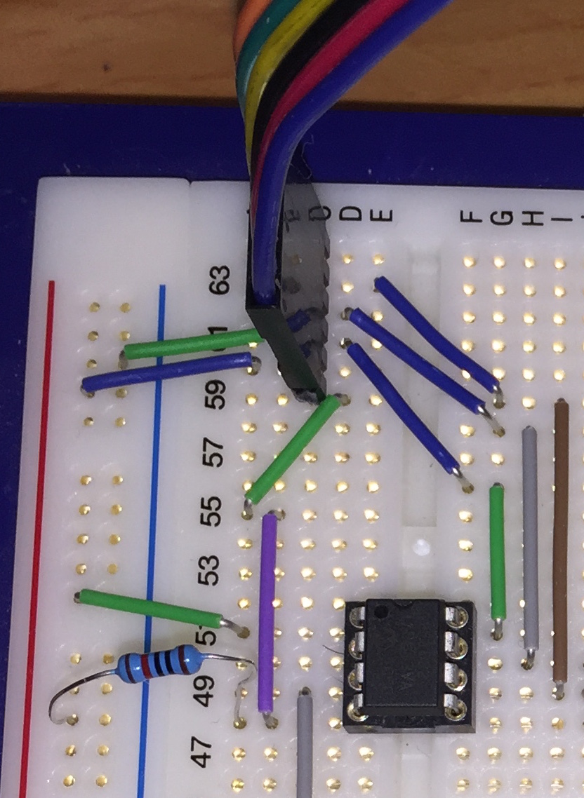
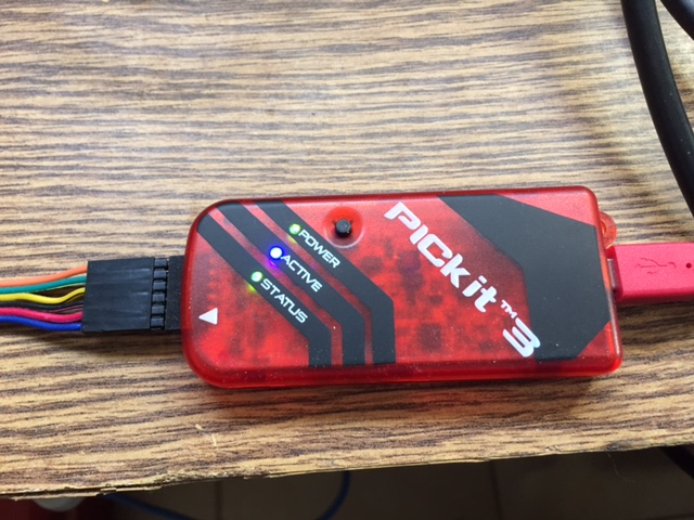
The following photo shows how the PICKit3 is connected to the chip.
The PICKit3 header has six pins and pin number 1 is identified by an arrow as can be seen in the next photo.
The pins have the following functions:
1 – VPP/MCLR
2 – VDD
3 – VSS (Ground)
4 – ICSP data
5 – ICSP clock
6 – LVP (low voltage programming)
We use only the first five pins since we are not working in low voltage programming mode.
The table below shows where each PICKit3 pin is connected to the chip.
[table id=3 /]
The last connection is a 10K pull-up resistor connected from VSS to VPP – pin 4 – of the chip.
Configuring the MPLab IPE (Integrated Programming Environment)
Open the “Advanced mode” window in the Settings menu and select “Power” on the left pane. Make sure that VDD is correct (it is not correct in the screen shot below) and uncheck the “Power target circuit from tool” check box, so that the chip will be powered from the power supply. The reason is that the tool can not provide enough power for programming when it is in-circuit.
Possible problems
I encountered the following errors before I found how to set this up correctly:
“Too much power drawn on VDD” – the VDD and VSS are not connected to the power supply but instead draw power from the PICKit3.
My first PIC project is a LED controller (henceforth referred to as “LC”) for my Quadcopter 1. The LC will receive commands over a RC channel and control four high intensity LEDs that I will connect to the underside of the arms of the quadcopter. I will describe the features of the LC in a separate post. This post describes the first stage of programming the LC.
In this stage I wrote code that allows me to control any number of LEDs (well, in practice I can attach only four LEDs to the PIC12F1822) by defining different properties for each LED. The code is object-oriented in the sense that the behaviour of each LED is defined in an instance of a struct (=an object) and functions operate on these objects. I considered implementing a full object oriented model in which the functions are also included in the struct, but I FEEL that the overhead of this approach is too much for the tiny PIC controller and the inefficient compiler (the free XC8) that I use.
The following video shows the LC in use with two LEDs that blink at a different rate. The yellow LED blinks three times and then waits while the green LED blinks five times and waits. These two LEDs can be used as indicators to the internal state of the LC which has a major state (yellow LED) and a sub-state (green Led).
So let’s describe the code.
The application consists of three files:
Main function with the main loop
LED Controller header file
LED Controller implementation
Main
I will start with the main function because it shows how the LC code is used.
Main.c starts with setting up the configuration bits. Then the ISR counts the number of times Timer0 overflows where each overflow happens every 0.25 of a millisecond. The calculation is as follows:
Timer 0 prescaler (PSA) is set to 8 which means that the timer counts at a rate of 1Mhz
On each overflow TMR0 is set to 6 so it counts 250 ticks before it overflows again.
Then the main function starts with initialising the ports and defining the LEDConfig instances for the two LEDs. Finally the main loop starts. After every 4 overflows of Timer 0 (which are more or less equivalent to 1ms) the main loop calls the HandleLEDs function that updates the state of the LEDs.
Note that main needs only instantiate the LEDConfig structs, pass them to the LC and then notify the LC once every 1ms.
LED Controller header file
The header file defines the “blink interval” and “off interval”, the LEDConfig struct and declares the functions that operate on instances of LEDConfig. The “blink” and “off” intervals specify the amount of time a LED is on or off while blinking and the amount of time it is off between bursts of blinking.
The C file manages the array of LEDConfig structs so that the user of this code (i.e. the main function in this example) needs only create these structs and pass them to the LC. Main must also notify the LED controller of every “tick” of the clock and the LC takes care of everything else.