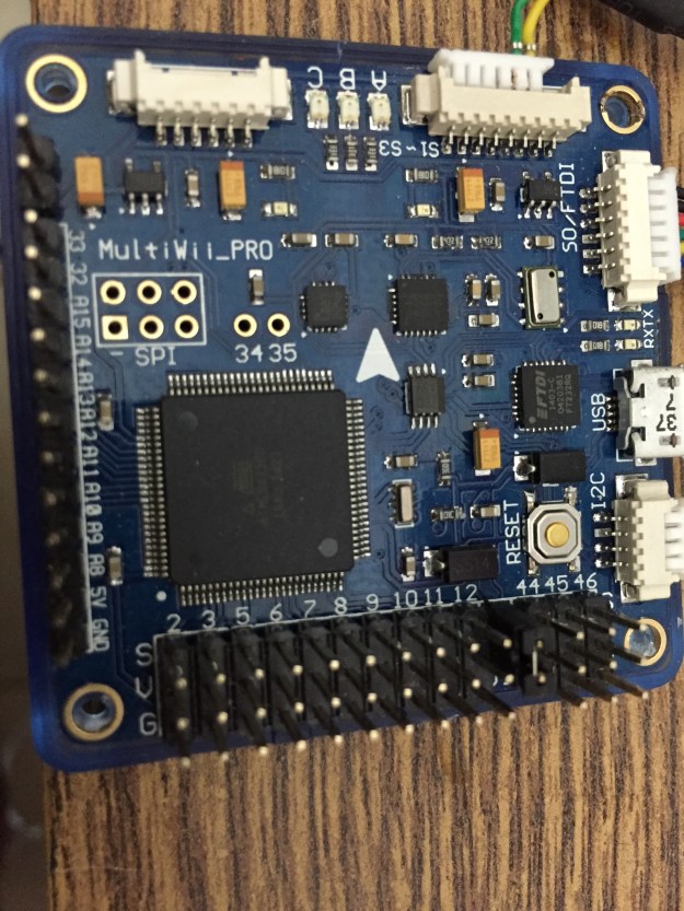
I started by connecting the HobbyKing AIO board to the GPS that I bought from HobbyKing for $35 and to the HC-05 Bluetooth module. This allows me to configure the AIO via BT.
The connections are as follows:
GPS to AIO board
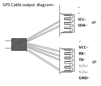
The UBlox Neo-7M GPS comes with a cable that has 2 mini-molex connectors, one with 4 pins and one with 5 pins.
Some changes must be made to these connections in order to fit them to the AIO board. Moving the cables between pins is simple – lift the flap that holds the cable inside the connector and pull the cable out. See the photo below.
The changes to cabling are as follows:
4-pin connector
The 4 pin connector is connected to the i2C connector on the AIO.
It should have the following cable connected to it, from top (leftmost) to bottom:
SCL – moved from pin 2
SDA – moved from pin 3
VCC – moved from the 5-pin connector
GND – moved from the 5-pin connector
5-pin connector
The TX and RX cables from the 5-pin connector must be connected to RX2 and TX2 on the AIO board respectively. So I replaced the 5-pin connector with a 6-pin connector that I had from the AIO package and connected the TX and RX cables at the right slots.
AIO board to HC-05 BT module
The BT module connects to the FTDI port on the AIO as follows:
AIO GND —> HC-05 GND
AIO VCC —> HC-05 5V
AIO – RX —> HC-05 TX
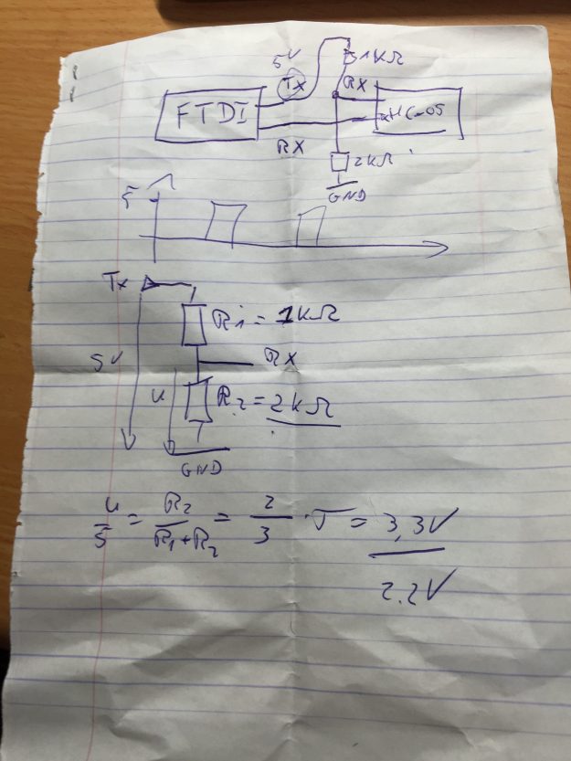
AIO TX is connected to HC-05 RC via a voltage divider in order to protect the HC-05. The HC-05 uses 3.3V while the output of the AIO board may be 5V. The following photo of a crumpled piece of paper shows the two resistors that form the voltage divider.
AIO external power
The AIO receives 5V power from an external source on the GND and VCC pins.
The HobbyKing AIO that I’m using in this project talks MAVLink with the APM console (or any other MAVLink management console). I decided to use BT for connecting it to the console so I borrowed a HC-05 module from my good friend Tomer.
The HC-05 comes configured for 38400 bps (bits per second) so the first step was to configure it to operate at 115200 bps.
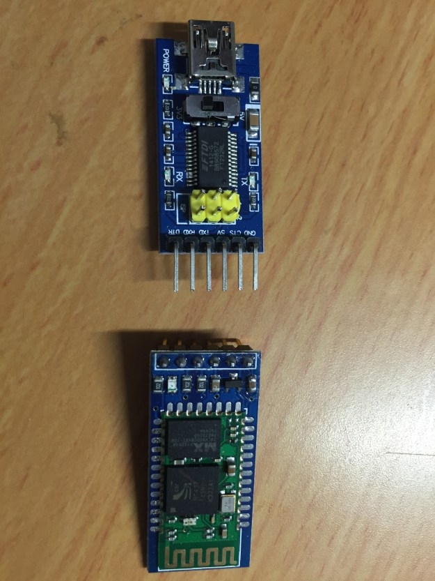
Configuration of the HC-05 is done with a FTDI board. I bought one on Ali express for $2.48.
Here are the HC-05 on the bottom and the FTDI board on the top:
This FTDI board has a switch that sets it to use 3.3V or 5V. Since the HC-05 is sensitive to voltages over 3.3 I used 3.3V.
The HC-05 enters configuration mode (via AT commands) when pin 34 is pulled high. On this board pin 34 is connected to “Key”.
The two boards are connected as follows:
FTDI ground —> HC-05 ground
FTDI TX —> HC-05 RX
FTDI RX —> HC-05 TX
FTDI VCC —> HC-05 Key
FTDI VCC —> HC-05 5V
Now the FTDI board can be connected to a USB port and you can use a terminal program (I used Arduino’s serial monitor) to connect to it. Remember that the connection speed is 38400.
Sent “AT” to the board and it should respond with “OK”.
To change the bit rate send “AT+UART=115200,0,0”. The board should respond with “OK” and it is ready.
My main goal is to control the UAS (unmanned aerial system) over the cellular network. This means that commands will be sent to the UAS over the cellular network and the video feed from the UAS to the operator’s console (a computer, or a cheap PS3 joystick) will also be transmitted over the cellular network.
There is nothing new in this approach by itself and people all over the net are doing it by putting a $50 Raspberry Pi running Linux on the UAS. My angle on this would be to try and achieve this goal with cheap hardware.
My development plan is as follows:
Build a good and stable UAS and get it to fly with the HK AIO controller – using the HK firmware
Compile the firmware from sources, configure it and get it to fly
Transmit commands over the cellular network
Transmit the video feed back over the cellular network
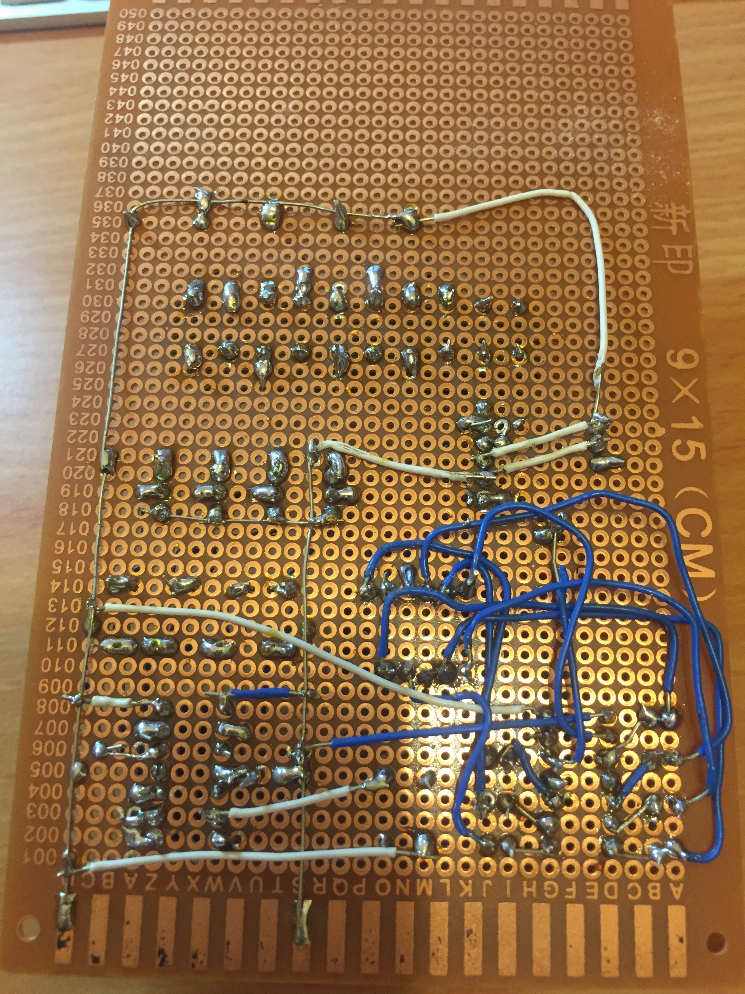
The time has arrived to move the LED controller circuit from the bread board to a real board. It was to be my first experience with relatively delicate soldering of quite a few connections. I stuck the few components onto the board and started soldering the underside.
I realised after a short while that I shouldn’t have placed cables on this side at all because the soldering will break if any pressure is applied to them. Also, after some cables were already soldered it because difficult to solder more of them, especially those connections that already lay under other cables. Anyway, most of the cables in the photo above connect the 7-segment controller with the 7-segment display.
On the left side of the photo you can see the two common ground an 5V lines that I connected to the board. This was very convenient.
I passed the rest of the cables on the upper side.
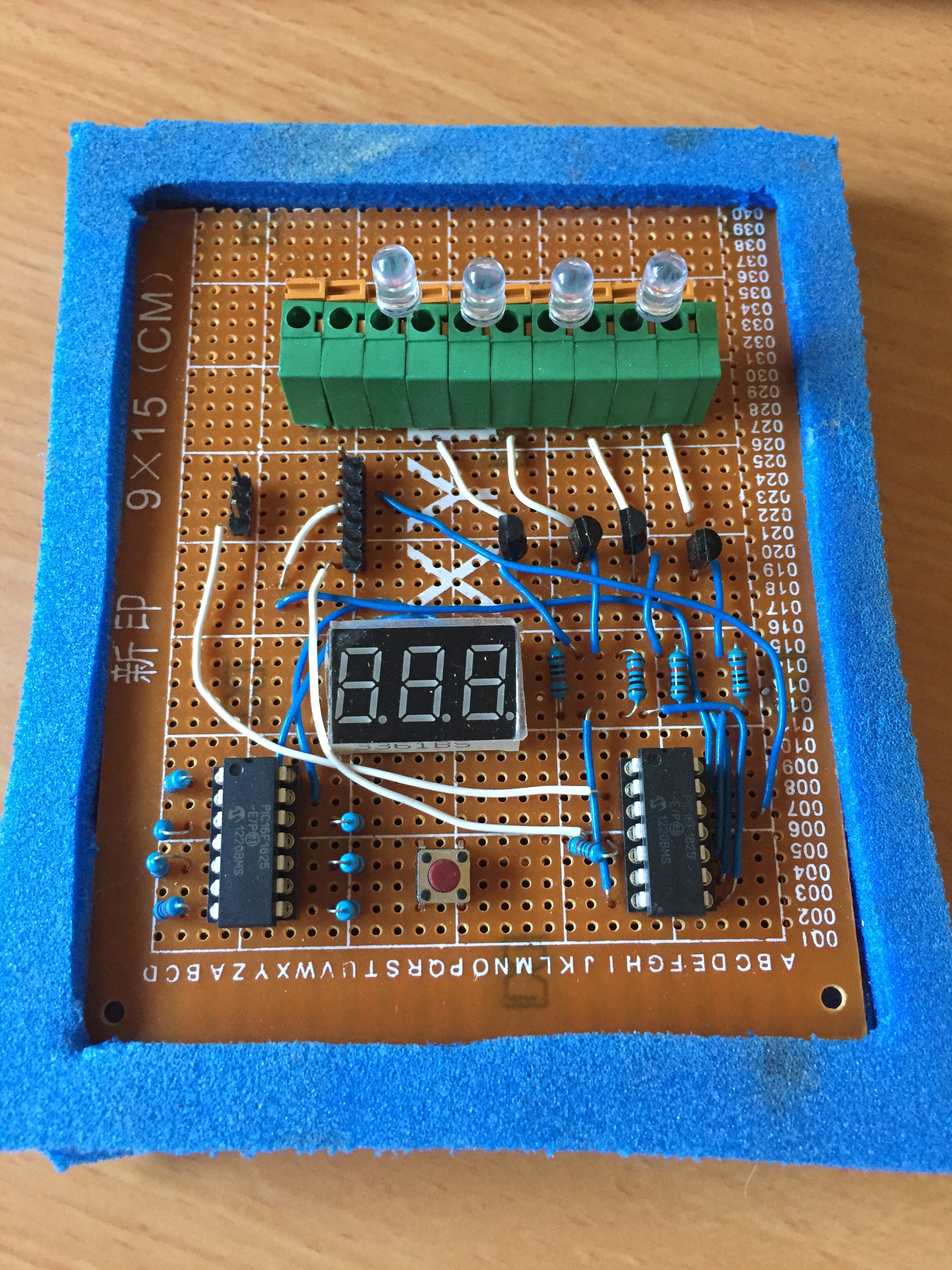
One of the nice features of the board is the old green connector that I salvaged from an old PC board. In this photo I connected LEDs for verification, but when I’ll mount it onto the quadcopter I’ll connect the cables attached to the LEDs. Getting it out of the original board was hard and attaching it to this board was even harder because its pins were wider than the holes in the board. I filed them for a long time and finally decided to hammer the piece (gently) onto the board. This worked.
And here is the board in operation.
I had to protect the cables running on the bottom side so I prepared a frame from two pieces of this soft plastic material whose Enlish name I don’t know. I cut the frame to be smaller than the board so that it will hold the board in place.
When I replaced the test LEDs with real high-intensity LEDS I found the following problems:
The high-intensity LEDs are rather dim. I didn’t debug this problem yet but I can think of two possible causes. One is that I used resistors that are too strong (220 Ohm).
I may connected the transistors incorrectly.
The transistors are not sourcing enough current.
I will have to talk to my friend Tomer about this problem.
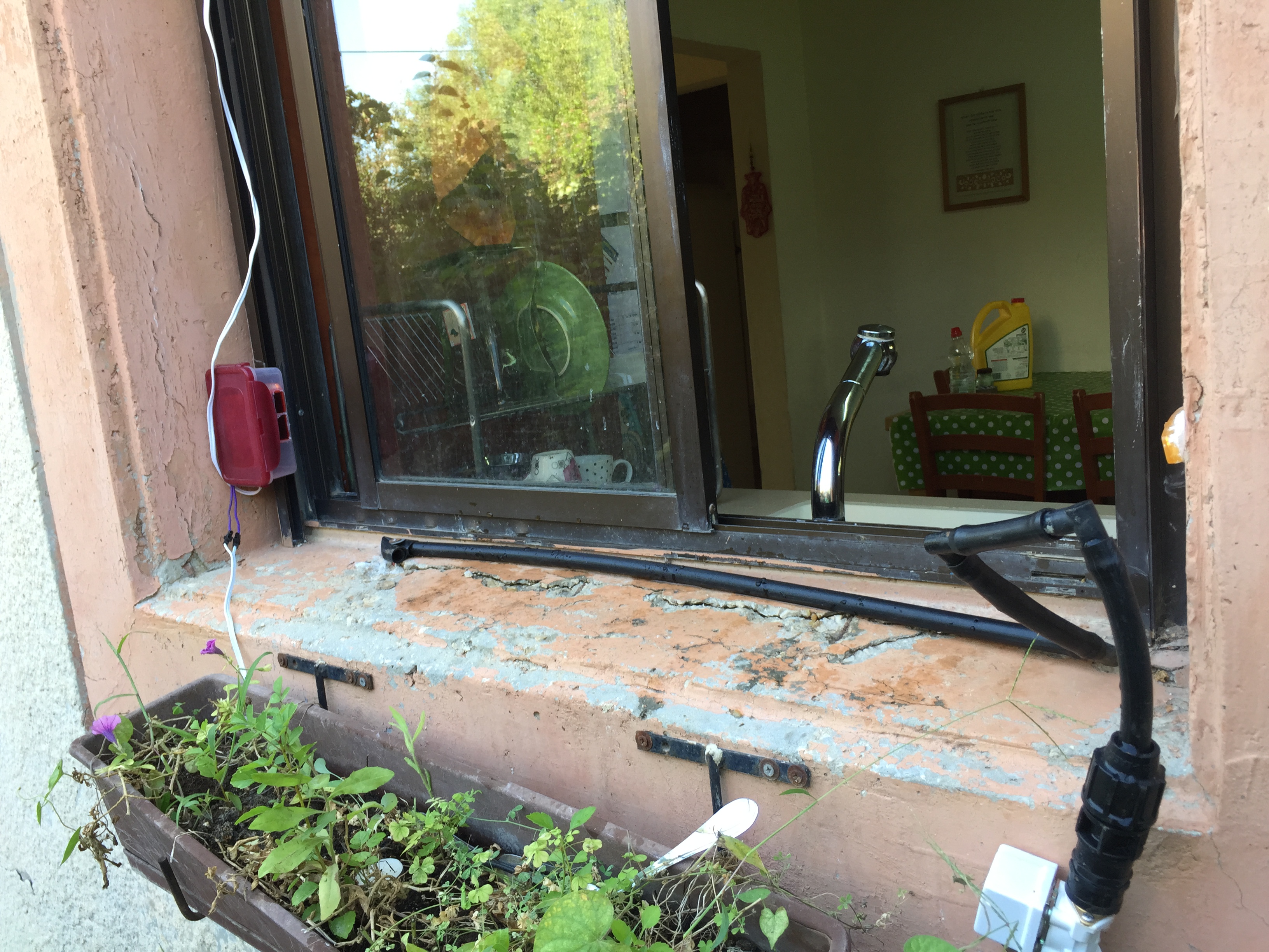
The electronic part of the CDS is relatively simple compared to its installation. I started by gluing the sensor box to the metal window frame with a 2-sided glue strip.
Then I found a small reflector on an old bicycle and glued it with plaster at the exact position on the opposite wall.
Some time passed until I decided to finally connect the water pipes to my automatic irrigation system. I did that only when I discovered a small hole in one of the main pipes and had to take it apart and replace that section of the pipe. So I added a T-shaped connector and drew a line towards the window.
One of the cats living in our backyard has been bothering us for a long time. We love cats, but this one keeps sneaking into the house, meowing loudly even when it’s not hungry and trying to steal food on every occasion (even though we feed it outside). When we have a family meal we can’t open the kitchen window because it jumps inside and then tries to jump on the table.
Nothing helped until my daughter came up with the idea for a Cat Deterring System, or CDS in short. CDS is based on cat’s fear (or deep dislike) of being wet. The idea is to install a motion sensor across the window that opens an electric tap when the cat jumps on the ledge and sprays a could of water. Simple and cool.
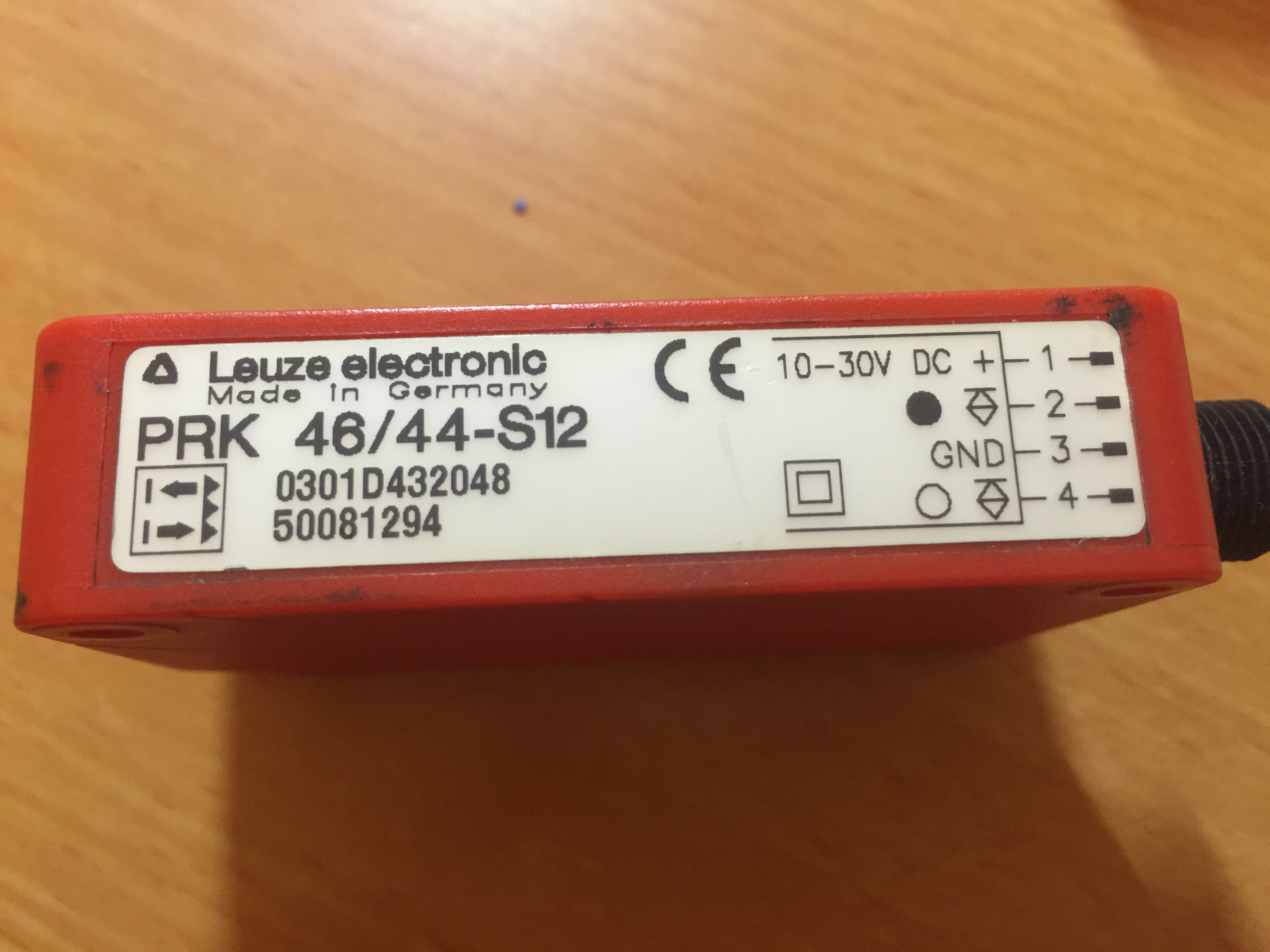
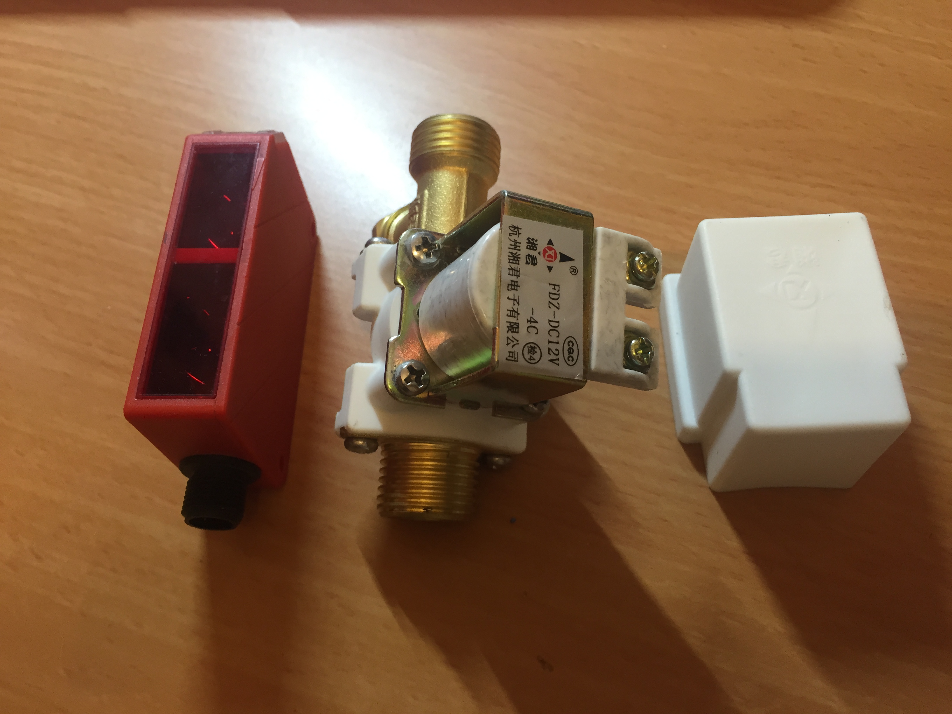
I started by ordering this sensor on eBay. I checked the prices right now and they are very high. I managed to buy 2 of these for just 10 Euro each. They now sell for much higher prices – between 30 and 100 euros!
I also ordered an electric solenoid valve running on 12V (as the sensor). These valves were rather expensive and I’m a bit surprised that I bought them just for scaring a cat away …
These components were lying on my shelf for several months before I finally got down to develop the system. But at some point my wife threatened that she would do something drastic about the cat so I had no choice. I didn’t want to find out what that may be.
The most difficult part was to understand who the sensor works. Quite early in the process I realised that I need a reflector to position opposite the sensor. I also needed to create a connector for the sensor because it didn’t arrive with one. The sensor has 4 connections, two for ground and 12V input and output pins – one is high when the beam is reflected (no obstruction) and on is high when the beam is blocked. My friend Tomer helped me with the connectors – 4 pins salvaged from an old serial cable.
I hooked up a simple circuit in which the output of the sensor connects an old 12V relay that I had at home and the relay opens the valve. I needed the relay because the output from the sensor could not hold the valve open. Tomer said I should have used a transistor and that a relay would not work fast enough but in fact a relay is just perfect, and I had nothing to do with it.
So I set up a small test rig to try and get the sensor to work.
After looking around for a reflector I found an old hologram which worked well. You can see it in the next picture. Unfortunately, the sensor is very sensitive and can detect the reflected beam only if the reflector is set just right. It took me a very long time to get it to work.
The video below shows the system in operation.
The sensor has two lights, a green one that indicates that it is on and an orange one. The orange light comes on when the beam is reflected properly. It blinks when the beam is detected but not perfectly. It goes off when the beam is blocked.
After many evenings and a long time of learning to use all the required resources of the PIC16F1825, here is the first version of the LED controller for my quadcopter. It requires some debugging but it works.
The video shows the test setup of the LED controller. The transmitter is on the right and the receiver is the small box between the transmitter and the breadboard.
The circuit on the breadboard consists of two PIC controllers, a 7-segment display, LEDs and some resistors. The left PIC controls the 7-segment and the one on the right controls executes the application.
When the video starts the 7 segment display shows a rotating segment for a split of a second. Then it enters the startup sequence for about 1 second. During this time the 7-segment displays 888 and all the LEDs light up. Then the 7-segment display shows the current mode and the LEDs enter this mode. The initial mode is 1 and all the LEDs are off.
Then I push the button that is associated to channel 6 upwards. This changes the PWM value on the channel and the modes start to change. There are 14 modes, so each mode corresponds to a range of PWM values and hence multiple presses are needed to switch to another mode. Notice how the LEDs change their behaviour when modes change.
There are still some bugs in the system. Notice how the number 154 appears on the display when I start pressing the button. This is because I configured the lower PWM value higher than the real minimum value. Also, the changing of modes is not smooth or predictable. This could be related to the non-linear configuration of the channel.
A few days ago I finally started writing the LED controller code according to the specification of the init sequence that is described in another post here. One of the first tasks is to light up the LEDs and the display as a self-test on startup. Lighting up the display means that I should show the number ‘888’ that lights up all the segments (except for the decimal dot that I don’t use in this project). At this point I realised that the serial receiver part can receive only one byte – numbers up to 255. So I decided to spend a bit more time on the 7-segment controller and enhance it in two ways:
Allow it to display sequences of patterns and not only numbers. The difference is this – when displaying a number the controller displays the same digits over and over again while a sequence shows a different pattern on every iteration through the main loop. The difference is a bit subtle because a number can be considered a sequence with just one state. Anyway, the youtube video below shows an example of a “sequence”
Implement a serial input protocol by which it is possible to send commands to the controller. The protocol is explained below.
Example of a sequence
This youtube video shows an example of a sequence.
The serial protocol
The previous version of the controller listened on the serial port and expected to receive a single byte each time that it interpreted as an unsigned 1-byte number. The new version expects a “packet” with the following structure:
Length – 1 byte. The length of the value parameter. This is a forward looking field because right now the lengths of the values are completely determined by the type field. However, I am preparing for passing strings in the future.
Value – variable length according the the Length field. If the value is a number it is transmitted MSB first.
Delay – 1 byte. The delay is multiplied by 50 by the controller and is used for the time period in which digit is lit. The unit is the Timer0 rollover rate.
Stop byte – 1 byte – value 0xFF. This byte serves to indicate ‘end of packet’ and as a simple check sum. The controller verifies that it sees 0xFF at the expected end of the packet.
The code
#include <xc.h>
// CONFIG1 #pragma config FOSC = INTOSC // Oscillator Selection #pragma config WDTE = OFF // Watchdog Timer Enable (WDT disabled) #pragma config PWRTE = ON // Power-up Timer Enable (PWRT enabled) #pragma config MCLRE = OFF // MCLR Pin Function Select #pragma config CP = ON // Flash Program Memory Code Protection #pragma config CPD = ON // Data Memory Code Protection #pragma config BOREN = ON // Brown-out Reset Enable (Brown-out Reset enabled) #pragma config CLKOUTEN = OFF // Clock Out Enable #pragma config IESO = ON // Internal/External Switchover #pragma config FCMEN = ON // Fail-Safe Clock Monitor Enable
// CONFIG2 #pragma config WRT = OFF // Flash Memory Self-Write Protection #pragma config STVREN = ON // Stack Overflow/Underflow Reset Enable #pragma config BORV = HI // Brown-out Reset Voltage Selection #pragma config LVP = OFF // Low-Voltage Programming Enable
The sequences below describe special effects of lighting segments of the display. Each record (a triple) represents the state of the 3 digits. A zero (0) indicates that the corresponding segment it lit while a (1) indicates that the segment is off.
The following 5 variables control the loop that lights up segments.
// control variables with sensible initial values int type = 4; int state_index = 0; int delay = 8; unsigned int number = 256; Sequence *seq = &(sequence[1]) ;
The set_digits function is called at the start of every “display” loop. It determines what should be displayed in the following iteration of the display loop. It could be a number where each display digit shows a digit of the number, or a different pattern of a sequence. /**************************************** * ****************************************/ void set_digits() { int remainder; unsigned char *s;
The process_serial_input function is called by the ISR whenever it sees a stop byte (the value 0xFF). The stop value is a valid value therefore this function returns 0 to indicate that a full packet was processed and a -1 to indicate that the buffer does not contain a full packet and more bytes should be acquired.
/**************************************** * ****************************************/ int process_serial_input() { int i; unsigned char ltype = 0; unsigned char len = 0; unsigned char ldelay = 0; unsigned int intvalue; unsigned char stopbyte = 0; unsigned char *buff = rxbuf;
ltype = *buff++; len = *buff++;
for (i = 0; i < len; i++) { intvalue = intvalue << 8; intvalue += *buff++; } ldelay = *buff++; stopbyte = *buff;
// Check the input for errors if (buff[2 + len + 2] != STOP_BYTE) // missing stop byte return -1; if (ltype > 4) return -1; if (ltype == 4 && intvalue > MAX_SEQUENCE_ID) return -1;
type = ltype; delay = ldelay; if (ltype < 4) number = intvalue; else seq = &(sequence[intvalue]);
return 0; }
The interrupt service routine reads bytes from the serial connection and fills the input buffer.
This code is not really debugged because of lack of time but it works. However, there is an interesting bug in the system that I don’t have time to fix. The problem is that every 256th number is shown as a zero (0).
I don’t know if the problem is in the controller, the protocol or the test app that send the numbers over the serial connection.
On second thought, this problem must be related to my use of the value 0xFF as a stop byte. I will have to research this a bit more.
As you could see in the video I of my 7-segment driver with serial input, the left most digit was flickering heavily. I decided to spend some time to improve the code. I did several variations of the program and finally settled on the following one.
In this new version I eliminated Timer0 and changed the timing of actions in the main loop. The flickering didn’t disappear completely but it became much much better.
/**************************************** * ****************************************/ void calculate_digits() { static unsigned int value = 0; int remainder;
while(1) { switch (state) { case 0 * INTERVAL: LATA0 = 0; LATA2 = 1; LATA5 = 0; if (overrun == 1) show_overrun_error(); else show_number(digits[digit2index]); break; case 1 * INTERVAL: LATA0 = 1; LATA2 = 0; LATA5 = 0; if (overrun == 1) show_overrun_error(); else show_number(digits[digit3index]); break; case 2 * INTERVAL: LATA5 = 1; LATA2 = 0; LATA0 = 0; if (overrun == 1) show_overrun_error(); else show_number(digits[digit1index]); break; case 3 * INTERVAL: calculate_digits(); break; } if (state >= 3 * INTERVAL) state = 0; else state++; }; }
I found something strange while working on this code. My main development computer is a MAC mini but it does not recognise my fake PICKIT3. Therefore I normally develop on a virtual Windows machine that runs under VirtualBox on my MAC. This time I decided to run the IDE on the MAC and run only the IPE (the programmer) on the Windows. When I compiled the code above on the MAC and downloaded it with Windows, the application behaved very strangely. It would suddenly crash, or come to a halt at random points in time. Other variations of this program caused a read overflow very quickly. It was very strange and nothing I did fixed the problem. So I went back to my normal environment and ran exactly the same code on the Windows machine and it just worked.
I will be very glad if anyone could explain why this happens. I did compare all the compiler settings, especially the optimisation settings, between the two computers and they are identical.
After learning how to use the various features of the PIC16F1825 controller that I need for building and writing the LED controller it is time for some planning.
First the HW. Following is a schematic diagram that I prepared with the Freeware version of the Eagle application for Mac. Here are the details.
It is an excellent app and I thank my friend Tomer for telling me about it. The freeware version is limited but completely suitable for my current educational purposes. I will even allow me to design a board if I choose to do so – the freeware version is limited to 10cm by 8 cm boards and this size is enough for my LED controller.
The application is a bit non intuitive, especially with the MAC single-key mouse, but after a bit of practice and watching this video, I managed to draw the whole schematic in about 1.5 hours.
So, here is my schematic diagram.
It looks a bit complicated but it is not. It consists of the following components:
[table id=4 /]
Most of the wiring in this diagram are for the 7-segment display. I think that the rest is self explanatory to some extent and will be clarified in the next posts when I start writing the SW.
I’m aware that this schematic is probably “on the face” as we say in Hebrew, which means very poor and I’m sure I will improve as we go.