היום התקשרה אלי מתאמת ההשתלות והזמינה אותי לאבחון פסיכולוגי בעוד מספר ימים. האבחון הזה הוא חלק ראשון מהשלבים הפסיכולוגיים של התהליך. לפי מה שהבנתי הם ינסו לבדוק אם אני מבין את כל ההשלכות, אם אני נמצא תחת לחץ כל שהוא ואם אני עושה זאת תמורת כסף. התשובות שלי הן: כן, לא ולא. מתאמת ההשתלות סוברת שאני לא צריך שום הכנה ולא תהיה לי בעיה לעבור את האבחון הזה. רק שאבוא כמו שאני
au-natural
אבל … בעוד כמה ימים אחרים, אוזמן לוועדה האמיתית ושם הם יקרעו לי את הצורה. כך אומרת מתאמת ההשתלות, נקרא לה מכאן ולהבא “ויקי”. אז לפני הוועדה הקורעת ויקי ואני נפגש והיא תכין אותי. שמעתי שהיא בעצמה ישבה פעם בוועדה הזו והיא יודעת מה קורה שם. יהיה מעניין
בחיי הארוכים כמעט לא נפגשתי עם פסיכולוגים, כלומר בהקשר המקצועי. אני דוקא מכיר פסיכולוג או שניים וגם נפגש איתם באופן חברתי. הפגישה הקודמת שלי עם פסיכולוג היתה לפני כעשר שנים. הוא עבד בחברת “ט…”. בראיון ההוא דוקא לא הצלחתי, לצערי היוקד. אבל הפעם זה יהיה הרבה יותר פשוט, זה לא אמור להיות אבחון אישיותי
בקיצור, יהיה מעניין ויהיה סיכום פה בבלוג. תמשיכו לעקוב ולהפנות אלי את כל חבריכם
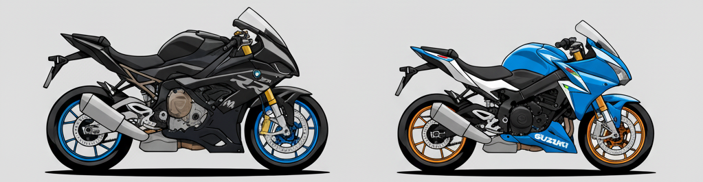
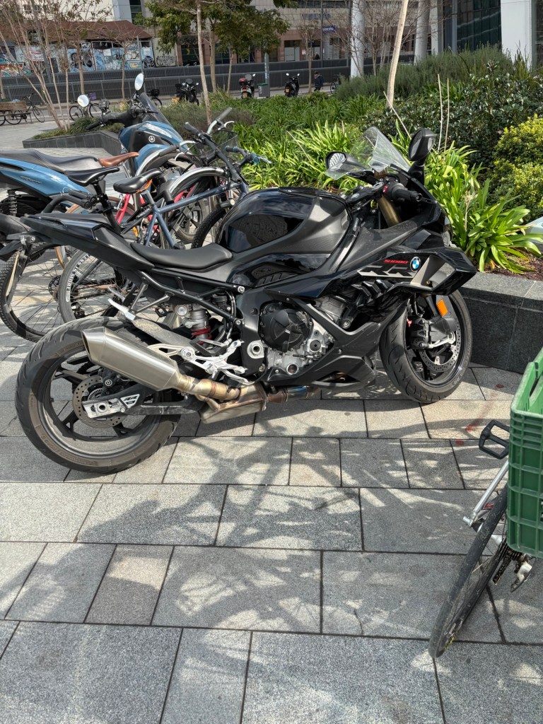
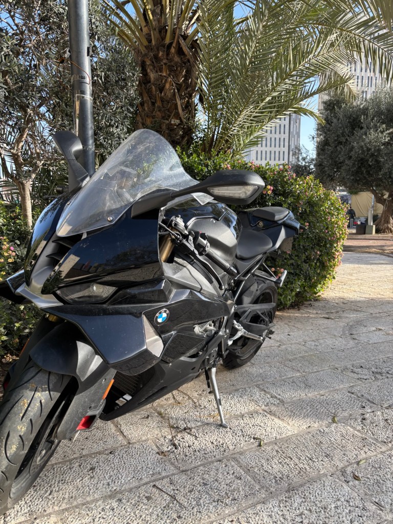
I rode 241,000 KM over 10 years and four motorcycles until my first accident. It’s very unfortunate that this first accident happened on my new baby. This Accident also shattered my belief that I’m the best driver in the world and I’ll be so forever or at least till my 120th bday. I thought I’ll probably be the only rider to achieve this feat but now all of this is gone. The good thing is that with this mindset, of being the best driver in the world, and riding on this amazing motorcycle, this accident would surely have happened at a much higher speed than the 5 km/h in which it happened, as I will explain.
I teach my kids that it’s our responsibility to prevent any accident no matter what, even if somebody hits you from behind it’s still your responsibility and you must try and escape. In this case, all the holes in the Swiss cheese lined up and my feeling of being invincible coincided with a dazed and inattentive driver standing at an intersection and instead of waiting a few seconds, I got myself into this situation. It is sometimes hard to practice what we preach …
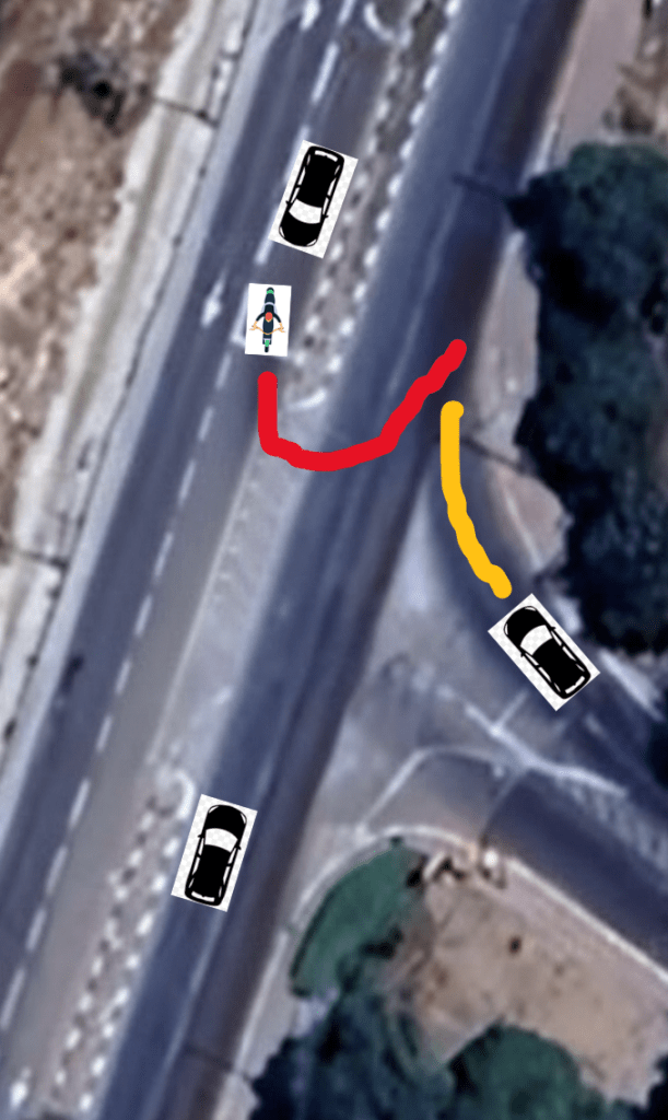
The accident happened at the intersection below, where I took a U-turn, the driver in the car on the left didn’t notice me (he said he was looking to the left) and he hit me from behind.
As I took the turn, I saw in the corner of my eye, a car moving towards me and the moment after I found myself lying on the road. I wasn’t wounded. Nothing really happened to me, so I stood up immediately, but I saw my poor baby lying on its left side. Some people who saw this came running towards us and asked me if I’m OK? I said: – Why are you asking about me? Its the bike that got hit … The bike is so light so I lifted it up by myself. The driver who hit me got out of the car and looked a bit dazed. He held some suspicious cigarette in his hand. He was so apologetic. He said he was looking to the left and driving to the right at the same time. He said I shouldn’t worry, he’ll fix the motorcycle for me. I looked at his old car and a doubt crept into my mind about this point. Just a few weeks ago, my daughter scratched a new car, just a tiny scratch, and the cost was 15,000 NIS (the Israeli currency – New Israeli Shekel) – charged to my insurance. And here there’s a BMW all scratched.
In Israel, after an accident, we exchange the insurance details, so I asked him for the insurance. – I don’t have it here, maybe its at my work I understood the situation very quickly in spite of the deep sorrow over my poor baby. – Ok, then, give me your phone number, I said. He gave me the number and let me photograph his ID card – Don’t worry, I’ll fix it up for you, he said again.
At this point there wasn’t much more to say, so I looked at the bike. It seemed to be ok but I was worried that perhaps the fork got bent, or something in its perfect alignment was broken. The car’s driver said goodbye and drove away. Friends later told me that I should have lain on the road screaming and demanded an ambulance and police. But I’m not doing things like that. I was equally sorry for my beautiful baby as for the unfortunate driver who hit me. So I decided to drive to the Petakh Tikva Service Center. After a few meters of driving I realized that the left handlebar was slightly bent. Not much, but noticeable and probably dangerous. So I immediately called Nahik, the Motorrad department manager at the support center and told him I’m coming. Nahik said I’m welcome.
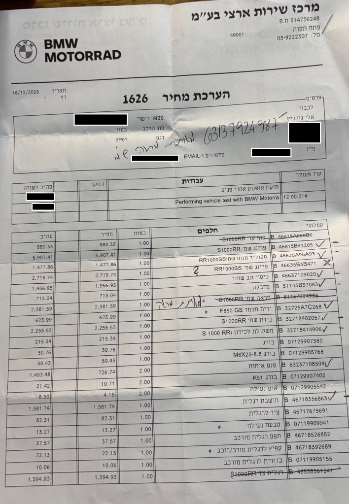
When I arrived, Edi, Nahik and the team were waiting for me. They took the motorcycle, verified that the handlebar is indeed bent and made sure that the fork is still straight and aligned, so I could continue driving for now. Edi also took photos of all the damages and said he’ll prepare a quote for full repair in 2 days. At the end it took 3 days because some of the parts were still not in the database – this was probably the first accident of a new S1000-RR in Israel. But after 3 days Edi sent me the quote. And by the way, the Service Center didn’t charge me anything for all this work.
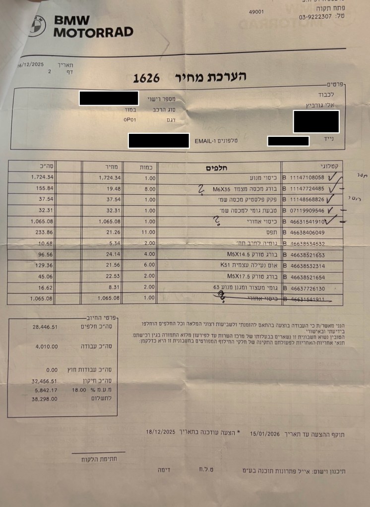
The quote was for a full repair with new parts for 38,000 NIS (around $11,300). Here’s the quote, so that you can get an impression of how much automotive parts cost in Israel.
I sent the quote to the driver who hit me and he didn’t reply. So I started considering the alternatives. On one hand I wanted to get the motorcycle fixed as soon as possible, at least the handlebar. On the other hand, if the car driver has insurance, then I can’t start fixing it myself, but I must follow the insurance procedure, and the guy wasn’t answering. After 2 or 3 days I understood that he doesn’t have any insurance and there’s no point in waiting. I left him a message saying that by now he should understand that I don’t want to cause him any problems and that he shouldn’t be so ungrateful. I asked that he at least tells me the truth about the insurance. To this plea I finally got a reply. He said: – By coincidence I cancelled the insurance just a day before the accident. I didn’t reply because I didn’t know if the cancellation takes effect immediately or only at the end of the month, and he’ll update me. I send a few more messages asking about the update, but there was no reply and he declined my phone calls.
Ok … so I understood there’s no point in waiting any longer. I paid 1600 NIS ($500) to an appraiser, just so that I’ll have an option to sue him in court. The appraiser came up with the same estimate – 38K NIS. But truly, suing in an Israeli court wasn’t a real option. The problem with our judicial system is that they don’t rule by law, but rather by their personal tastes and inclinations. I could imagine myself falling into the hands of a progressive left-socialist judge (many of them are like that) which finds it appalling that the rich BMW driver (more on that in the next post) is suing a poor victim just because he nudged the motorcycle a little bit … So I left the matter of payment to God and started the fix.
I left the guy one last message saying that I had to pay the appraiser because he doesn’t answer. I got no reply.
I went to see Edi again and we marked all the essential parts on the price quote – these are all the markings you see on the page. I considered buying parts in Germany, which would have cost half the listed price. But then I decided that I had enough riding with a bent handlebar and a friend introduced me to Victor – a master car body repairman. So I fixed the handlebar at the Service Center and paid the full price. Then, for all the scratched metal and broken plastic parts I went to Victor (I’ll give his contact details privately to anyone who needs help). He took the motorcycle for 3 days and returned it fixed almost as new. All in all, the fix cost 7000 NIS ($2180) and my beloved bike returned to its beautiful self. The only thing missing is the sticker with the S1000 RR logo which costs 713 NIS and I didn’t buy it for now.
I didn’t call the car driver again after the last message about the appraiser and I simply gave up. But, in a great surprising twist, just a few days ago, he left me a message: – Please send me your bank details and I’ll transfer you the money and the next day 8500 NIS appeared in my bank account.
So this episode is behind me. I would like to thank the staff at the Petakh Tikva Service Center for all their help and support!
חשבתי להמשיך בעמימות הכללית השורה על הבלוג הזה לעוד זמן מה, אבל אני חש שזה מתחיל לשעמם. לכן החלטתי להסביר מה הרקע לבלוג הזה – מה הנושא המרכזי שבו ידובר בעתיד הקרוב.
למרות שהכוונה המקורית בבלוג היתה להשאיר אותו די סודי, או אולי לספר עליו למספר מאוד מצומצם של אנשים שיוכלו להפיק ממנו תועלת, מצאתי את עצמי בשבועיים האחרונים בודק את נתוני הכניסה לבלוג כמה פעמים ביום. כנראה שהאקסהיביציוניסט הפנימי שלי התעורר ומצא לעצמו מדיום חדש.
ובכן …
החלטתי לתרום כליה לחברה. לא חברה חברה, אלא חברה של המשפחה, ובעיקר חברה של התנינה שלי.
למען האמת, אני בעצמי לא רואה בכך ביג דיל גדול במיוחד, אבל אני מבין שזו החלטה די יוצאת דופן. ולכן החלטתי לכתוב עבור האנשים שעומדים בפני החלטה דומה ועבור עצמי – אוכל אולי לקרוא את הפוסטים האלה בעתיד הרחוק ולהזכר איך ומה היה. כמו כל ארוע, גם זה ישכח והחיים הרגילים ישתלטו על זכרונותי, אבל אולי באמצעות הבלוג אוכל לחזור לפעמים לתקופה הזו, שהיא אחת המענינות והטובות בשנים האחרונות ולהזכר.
מי שקרא את הפוסטים הקודמים חש כבר שזו לא ההתקלות הראשונה שלי עם הממסד הרפואי. אני חושב לשלב בבלוג הזה סיפורים מהעבר עם תאור של החוויות בהווה. סיפורי העבר ישארו מעורפלים, או שיתבהרו בעתיד, אבל לגביהם לא ינתן הסבר מפורש כמו בפוסט הזה. אבל אולי אחליט אחרת בעתיד. בקשר להווה, אני לא מתכנן לספר הכל בפרטי פרטים, אלא להדגיש את הנקודות והאנקדוטות המרכזיות בתהליך הארוך של התרומה. אולי באמת זה יעזור למישהו בעתיד.
יתכן שלמען האתנחתא הקומית אשלב קצת פוסטים שלא קשורים לכליות ולא לחוויות רפואיות אחרות, אבל, הכל יהיה אמיתי לגמרי. למעוניינים, יש בטקסטים רמזים וקטעי מידע קטנים מהנושאים האחרים שבהם אני מתעניין – רוסיה, סוציולוגיה, קומוניזם ונושאים מעין אלה. אולי בעתיד מישהו ילהק אותי לתוכנית “היפה והחנון”?
אולגה קיבלה מכתב מהמועצה המקומית שמפצירה בה לנהוג בזהירות. הלואי שאולגה היתה יכולה לעשות משהו חוץ מלשכב ולשבת על כסא גלגלים וחבל שבמועצה מקומית כזו קטנה לא בודקים מה שולחים למי. זה לא נשמע לי כל כך מסובך
לפני שנה אולגה קיבלה צו ראשון בתהליך הגיוס לצה””ל. בתחילה חשבנו להתעלם. מקסימום ישלחו צוות של המשטרה הצבאית לבית הספר לחינוך מיוחד שבו היא נמצאת. אח””כ החלטנו בכל זאת למלא את הטפסים לשחרור מטעמים רפואיים. הלכתי לדבר עם הרופאה הנפלאה שלנו שבאה לבקר אותנו בבית כשאולגה מרגישה לא טוב וחותמת לנו על כל הבקשות ממש בכיף. ישבתי עם הרופאה ומילאנו את הטופס. הסעיף העיקרי היה סעיף הדיאגנוזה הרפואית
טוב, אמרה הרופאה, בוא נראה מה יש לנו – אפילפסיה, עוורון קורטיקלי, טטרפלגיה ספסטית ופיגור –
זה הכל? שמחתי היתה מהולה במעט עצב בגלל כל הליקויים, אבל זהו, רק ארבעה ליקויים –
יש פה עוד סעיף, אמרה הרופאה, הם רוצים שאכתוב אם היא יכולה להתגייס –
הרופאה הרימה את העט על מנת לסמן את המשבצת הנכונה אבל אז עצרתי אותה
את יודעת מה, הצעתי לרופאה, למה בעצם שלא תתגייס? את יכולה להחליט שהיא לא יכולה להתגייס? יש לה הרי רק ארבעה ליקויים. כל מה שהיא צריכה בצבא זה מחלקה של בנות שיטפלו בה 24 שעות ביממה, אבל זו בטח לא סיבה לא לגייס אותה. אני בטוח שיוכלו למצוא בין כל הפקידות כמה בנות שתוכלנה להתגייס לעניין
שנינו פרצנו בצחוק
שלשום דיברתי עם מתאמת ההשתלות במחלקה. כל הבדיקות שלי בסדר. התיק מוכן ונשלח למשרד הבריאות. עכשיו מחכים לתור למבחנים פסיכומטריים. יתכן שנקבל תור בשבוע הבא
אולגה קיבלה מכתב רשמי מלשכת הגיוס. מפקד הלשכה החליט לפטור אותה מחובת גיוס מטעמים רפואיים. דוקא לא הציקו לנו בכלל. רק שני טלפונים לתזכורת שאשלח כבר את הטופס הרפואי וזהו. לא בדיקות ולא ניג’וזים אחרים. כל הכבוד לצה””ל
ההגנה שלנו פיספסה לשניה וג’ונריד קיבל את הכדור. הוא רחוק ממני רק ארבעה מטרים בצד שמאל ולוקח צעד קדימה בשביל לבעוט ברגל ימין. אבל … אני יודע ששום דבר לא יעזור לו. הגוף שלי עובר למצב אוטומטי, השליטה אינסטינקטיבית לגמרי, המוח לא חושב. אני מתקדם צעד קדימה בשביל לסגור לו את זוית הבעיטה. רגל ימין שלו מתרוממת באויר ואני יודע שהוא הולך לבעוט. הגוף שלי מתחיל ליפול ימינה. הידיים מתקפלות אל הגוף כדי לשמור על הפנים והאגרופים קפוצים בתוף הכפפות היקרות שהחברה קנתה לי לכבוד המשחקים בליגה למקומות עבודה. אני מרחף באויר, חצי מטר מהרצפה כשהכדור פוגע בידי ונהדף לצד ימין של המגרש. גופי הקשיש נוחת על הרצפה אבל זה לא מפריע לי בכלל.
כרגע איבדתי רבע שניה מחיי הקוגניטיביים. אין לי באמת מושג איך קרה שאני שוכב על הרצפה, מרגיש את כאב המכה בידיים ובצד ימין של הגוף, ומגלה שהכדור לא בתוך השער אלא בצד ימין של המגרש, נעצר ברגליו של קלאוס פוקס, חברו לקבוצה של ג’ונריד. התאור לעיל הינו רק שחזור הגיוני של סדר הארועים אין לי שום רי-קולקציה של מה קרה ואיך. אין גם זמן לחשוב על כל זה ולהצטער על רבע השניה האבודה. אני חייב לזנק חזרה לעמידה ולסגור את הפינה השניה, שכן אני מבין שקלאוס שוקל לבעוט ממרחק של עשרה מטרים. לו מוחי היה פועל ברגע זה הייתי מגחך לעצמי. אין שום סיכוי שבעיטה מעשרה מטרים תכנס לשער. אני ב-FLOW, בזרימה. אני סוגר נכון את הפינה השניה, קלאוס בועט בחצי גובה. הגוף שלי מתקפל, הכדור פוגע בבטן והידיים שלי סוגרות על הכדור. זהו, נגמרה ההתקפה. הלכה עוד רבע שניה של קוגניציה. תרגיע, תרגיע, צועק לי וסילי, לאט, לאט, תמצא שחקן פנוי. הוא צועק בלי פסיקים, אבל נראה לי שהם דוקא משדרגים את חווית הקריאה. אני מוסר את הכדור ומסתכל אחורה על מנת למצות את הרגע ולהתבשם ממבטי ההערצה של השחקנים שיושבים בחוץ ומחכים לסוף המשחק. אני ב-FLOW, אף אחד לא יכול עלי.
לפני כמה שנים השתתפתי באחת הסדנאות שמחלקת ההדרכה מארגנת מידי פעם, כנראה סדנא לניהול הזמן. המרצה או המרצה (ההבדל היה עשוי להיות ברור יותר עם ניקוד) הסבירו שלפעמים אנחנו נכנסים למצב של זרימה, של FLOW. במצב הזה אנחנו בשיא היכולת שלנו, אנחנו מרוכזים במשימה שלפנינו והכל מצליח לנו. גם המזל זורם איתנו, כמו שקרה כמה פעמים הערב.
היום הייתי ב-FLOW. שיחקנו שבעה משחקים רצופים וחטפתי גול אחד בלבד. תמיד אהבתי להיות שוער. לשוער יש את התפקיד הכי מאתגר במגרש, הביצועים שלו הם הכי יפים ומדהימים והוא צריך תכונות מיוחדות. לא צריך להיות כל כך בכושר ולא צריך טכניקה של שליטה בכדור, צריך אינסטינקטים חייתיים ולא לפחד. תמיד אהבתי להיות שוער, אבל בערך עשרים שנה לא שיחקתי. למדתי, גידלתי עם התנינה שלי את אולגה ועבדתי. רק לפני שנתיים חזרתי להיות שוער ואני מגלה שלמרות הגיל, האינסטינקטים חייתיים כמו שהיו והפחד עדיין לא משחק בי. אני משחק כל שבוע עם בחורים צעירים, חלקם עדיין בצבא, חלקם שחקני עבר בקבוצות נוער וחלקם משחקים בליגות לקטרגל ולעמוד בשער מולם זה אתגר של הלייף. או לפחות של רבעי השניה הנעלמים. אני זוכר את דינו זוף, קפטן נבחרת איטליה שזכה בגביע העולם כשוער בגיל ארבעים. אני כבר עברתי אותו ולכן אני לא משחק בנבחרת ישראל אלא כאן, במתנ”ס.
אז הייתי ב-FLOW – ואני נזכר …
– למה את חושבת שמה שקובע זה ה-FLOW? לפי המחקר שאני מחזיק בידי מה שקובע זו הפרפוזיה!!! אומר, כמעט בצעקה עו”ד אוליאנין (שם בדוי) שמייצג את הדסה (שם אמיתי).
– לא. אתה טועה, שניהם חשובים באותה מידה, עונה בתקיפות מאשה פטרובנה, ד”ר קושקה (שם בדוי). רואים שהיא מתחילה להתעייף. היא לוגמת מכוס המים שלה ומנגבת את מצחה. מתנהלת פה מלחמה ואנחנו יושבים ביציע הכבוד. המלחמה היא על מקצועיותה של ד”ר קושקה, על המוניטין שלה וגם על עתידנו. קשה לדעת מה מכל אלה חשוב יותר לד”ר קושקה אבל בנתיים היא מחזיקה מעמד בכבוד. הרבה דמים עלתה לנו ההצגה הזו. עשרים ואחת אלף ש”ח בשביל חוות דעתה הכתובה של ד”ר קושקה ובערך חמשת אלפי שקלים חדשים עבור ההופעה של היום. אפילו שלמה ארצי לא לוקח מחירים כאלה, אבל אין מה לעשות, אלה התעריפים. איך בכלל הורים לילדה כמו אולגה יכולים לגייס סכומים כאלה? תענוג כזה מגיע בקלות למאה אלף ש”ח והתוצאות לא מובטחות בכלל. בדיוק כמו שאומר העו”ד שלי לענייני תעבורה, מר סגל (שם אמיתי), אתה יודע איך אתה נכנס לבית המשפט אבל לאף אחד אין מושג איך תצא. כן … גם נהיגה מהירה היא תחביב יקר.
– בחוות דעתך כתבת שההרדמה התנהלה ב”רשלנות פושעת”! את לא חושבת שזו טענה מוגזמת ומיותרת? שואל בכעס מעושה עו”ד אוליאנין. ברור לי שבשבילו זה רק משחק. את שכר הטרחה שלו הוא מקבל בכל מקרה. בשבילנו זה עניין הרבה הרבה יותר רציני. זו העזרה שציפינו שד”ר עמלק יציע לנו בלי כל הטרחה הזו. אמרתי כבר שהיינו צעירים ותמימים?
– לא, בכלל לא, עונה ד”ר קושקה. איך היית אתה קורא לפרוצדורה רפואית שלא נשאר ממנה שום תעוד אמין. תראה מה הולך פה בתיק!! שני דוחות של מהלך ההרדמה שעל אחד מהם כתוב: “הדו”ח המקורי אבד, שוחזר מזכרון”. אין בכלל דו”ח של טכנאי ה-BYPASS (מכונת לב-ריאה). שני דו”חות ההרדמה שונים זה מזה. השעות שכתובות בדו”ח ההרדמה שונות מהשעות שרשומות בדו”ח האחיות ובדו”ח של המנתח. איך אתה היית קורא לזה עו”ד אוליאנין?
כן, קצת עצוב … אני נזכר באותו ערב בפגיה. ישבתי עם אולגה בת השבועיים על הידיים כשניגש אלי אדם צעיר וסימפטי והציג את עצמו כד”ר מילגרטר (שם אמיתי – שם רשעים ירקב). הד”ר חזר לפני זמן מה מהתמחות בארה”ב. הוא השתתף בשלוש מאות ניתוחים כמו שאולגה צריכה. הוא מומחה אמיתי. אותו מילגרטר בא לבדוק את אולגה עשרים שעות אחרי הניתוח. אולגה שכבה על הגב, רגליה מתוחות בטונוס נוראי ומשוכלות. בשלב הזה התנינה שלי ואני היינו כבר מודאגים מאוד מאוד. אולגה פתחה את עיניה אבל לא הגיבה אלינו בכלל. ניסינו הכל והיא לא הגיבה, רק שכבה כשכל גופה מתוח. הבטנו במילגרטר בתקווה ואמרנו לו שהיא מעולם לא התנהגה ככה – למה היא משכלת את הרגליים בצורה כזו?
– זה בסדר, היא ב”זולה”, הסביר מילגרטר.
אני כותב וליבי נצבט מחדש. בשלב הזה עדיין אפשר היה לעשות משהו כדי להמעיט את הנזק למוחה של אולגה אם רק המומחה הגדול היה מבין את מה שכל מורה לחינוך מיוחד מזהה מיד כפגיעה מוחית. רשלנות פושעת …
את ד”ר אופניים (שם בדוי למחצה) ואת ד”ר אפרוח (שם סוגסטיבי,התפרסם לאחר זמן כרופאו הכושל של אריאל שרון), שני המרדימים, לא ראינו בכלל אחרי הניתוח. האמת, גם אני הייתי מתבייש להראות את פני ליד אולגה.
המלחמה נמשכת.
– את כותבת שאת מומחית להרדמת ילדים, אבל אני לא רואה איפה התמחית בכך? שואל בציניות עו”ד אוליאנין.
אנו מרגישים שד”ר קושקה מתחילה קצת להתפתל. האם קנינו חתולה בשקית?
– לא התמחיתי באופן רשמי, אבל אני מרדימה ילדים כבר הרבה מאוד שנים ובקיאה בכל הספרות בנושא.
– אם כבר הזכרת ספרות מקצועית, עט עליה עו”ד אוליאנין, אני רואה שאת מצטטת מאמרים משנת 1996 כשהניתוח היה כמה שנים לפני כן. האם גם אז חשבו שה-FLOW והפרפוזיה חשובים באותה מידה?
– כן. עונה ד”ר קושקה בתקיפות. הסטנדרטים לניהול ההרדמה שהיו בתוקף בזמן הניתוח קבעו באופן חד משמעי שה-FLOW צריך להיות בסביבות השלושים ובניתוח הזה, אפילו לפי הרישומים הפיקטיביים בתיק, ה-FLOW יורד עד עשרים. מעולם לא ראיתי ניתוח לב פתוח עם ערכים כאלה! ד”ר קושקה ממשיכה להלחם בגבורה והבטחון שלנו עולה למרות שגם אני תהיתי איך אפשר לצטט מאמרים שנכתבו כמה שנים לאחר הניתוח כאסמכתאות לדרכי פעולה שהיו צריכות להנקט במהלך הניתוח. אבל כנראה שככה זה בהרדמה. נראה שהיא עומדת יפה מאוד בחקירה הנגדית של עו”ד אוליאנין ומעבירה את המסר שמדובר ב”רשלנות פושעת”.
אני נזכר בכל זה באילו מתוך חלום … ואני מתעורר לאט להווה. מוזר שאתמול התאהבתי מחדש בשיר של מדונה שנקרא: Love Profusion – פרופוזיית האהבה. נכון שהמשמעות של פרופוזיה קצת שונה מהמשמעות של פרפוזיה (נא לשים לב לאות השלישית ששונה בין המילים) אבל זה כמעט אותו דבר. שמעתי את השיר היום הלוך ושוב לאורך חמישים ק”מ בדרך הביתה וחשבתי שמה שאולגה היתה צריכה באותם ימים זה רק עוד כמה יחידות פרפוזיה של חמצן והיא היתה יכולה להיות בריאה. אפילו בלי אהבה, רק חמצן.
חשבתי שעוד מעט ויאולה תוכל לצטט לי את שורת הפזמון מהשיר: I got you under my skin. לא, לא מה שאתם חושבים. תחשבו יותר בכיוון של הפוסטים האחרים בבלוג הזה.
– – – – – – – – – – – – – – –
הערה לסיום: קלדנית בית המשפט כנראה לא קראה את התיק לפני הדיון ולכן במקום FLOW היא רשמה פלור. זה קצת מפריע לקריאה השוטפת של הפרוטוקול, אבל מתרגלים.
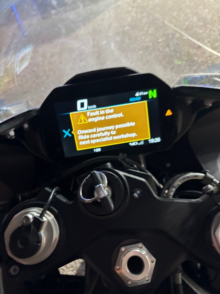
After about 3000 KM, suddenly a fault message appeared. I was alarmed at first, but, as it states, “onward journey possible” so I continued riding and the fault went away. After 600 KMs it appeared again and this time I decided to go to the BMW Petakh Tikva Service Center to have it checked.
At the center they connected the diagnostics terminal but couldn’t find the fault even in the history folder. They took out the motorcycle to a long ride, but it did not appear.
Since then it flashed again for a moment but didn’t even leave the yellow warning triangle (as it appears in the photo below).
So I’m wondering what to do and how to diagnose the problem. So far, it seems that the operation of the motorcycle is not affected and I’m not bothered by it very much.
But, if anyone from BMW ever reads these words, please update your SW so that if a fault is indicated, then keep it in the history folder. You can’t send the rider to a workshop only to discover there’s no trace of the problem. Thank you in advance.
The running-in period of 1000 KMs lasted about a week and I made a reservation for the first maintenance appointment at the BMW Service Center in Petakh Tikva, a town on the outskirts of Tel Aviv. The service center is located only 300 hundred meters from the site of my former beloved employer – Intel.
When I imagined how a BMW service center is like I had very limited success because, unfortunately, I’m an software engineer and not a poet. As the matter stands, SW engineering is not really an engineering discipline – its not like building a bridge that can stand up to daily traffic. Its more about building these bridges in one’s imagination, so imagination is involved, but in a structured way. So I’ll try my hand, in this post, at structured poetry.
We learned in the army that every good thing is divided into three parts. When referring to the BMW Petakh Tikva Service center, these three things are:
Facilities
The Service
And the most important – the human touch
So lets dig in, and start with the human touch.
The human touch
Since December 1st I rode already almost 4000 KM and visited the service center 5 times. This is, of course, a large number of visits and the reasons for this large number will become evident in the following posts in this blog.
The important point is that after these 5 visits I feel that the staff of the Motorrad department are my good friends and I trust them with anything related to my new and precious motorcycle.
When I first entered the service center for the running-in (1000 km) maintenance call, I met Edi, the service specialist. Edi welcomed me pleasantly and explained the procedures and options for everything. Most importantly, he gave me his phone number and said I can call or text him for anything, and I already used that option not once. Soon after the first visit, I needed extra help and Edi spent time with me, collected information, revised the information, browed parts databases online with me and all of that for no extra charge, kindly and pleasantly.
On my first visit I also met Nahik, the manager of the Motorrad department. Nahik also gave me his phone number and asked to call him immediately for any issue, which I did just one day later.
I met Eli, the workshop manager who patiently explains everything and answers all my questions. I also spoke with some of the mechanics who also answer every question and explain what they are doing (and of course, the customers are expected to stay out of the workshop area for most of the time).
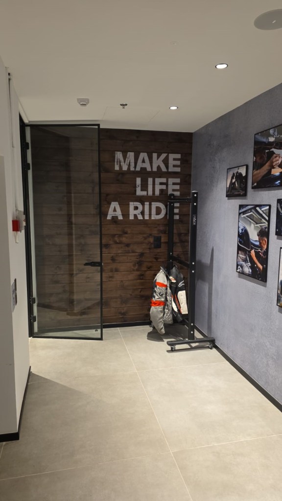
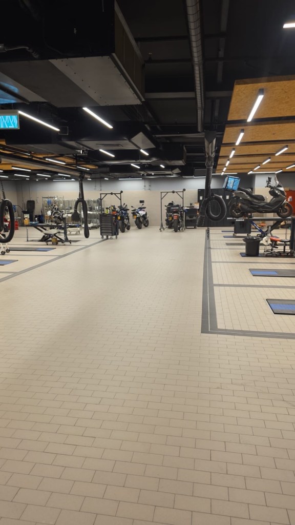
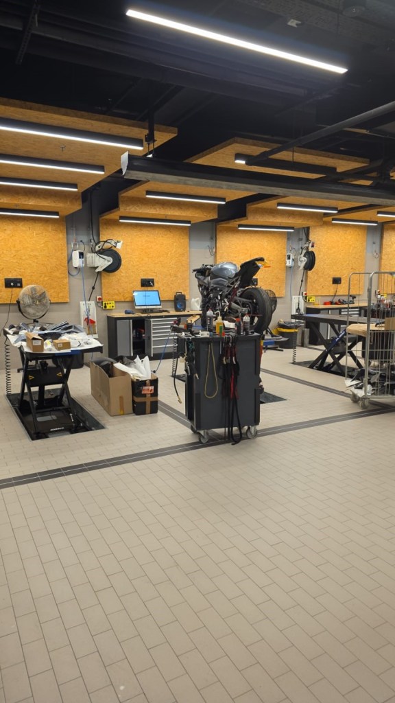
Facilities
The first thing I noticed when I entered the motorcycle department is the total cleanliness – even cleaner than in hospitals, and I scored quite a large mileage in hospital’s as you’ll be able to read in the Hebrew parts of this blog.
There’s a jacket and helmet hanger in the entry hallway.
Here are some photos of the workshop area.
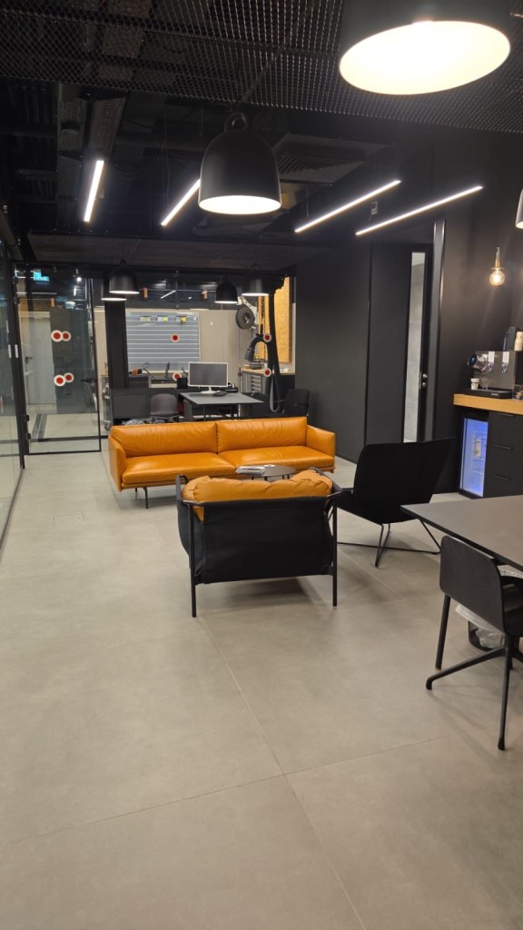
The customer waiting area is separated from the workshop by a glass wall. The waiting area is spacious and comfortable with 2 sofas and a large desk on which I can sit and work on my laptop.
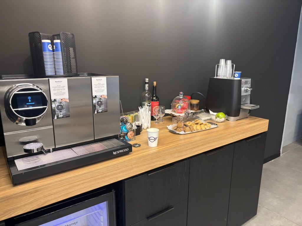
What really sets BMW apart from all the other service centers that I visited are the snacks, fruits, a coffee machine, Coca Cola cans (!) and even alcoholic drinks (!!!).
Free food is a great benefit. In one of the recent company meetings of NVIDIA, Jensen admonished the assembled employees and said something like: – You are all millionaires here, so why, when there are some refreshments outside, do you storm the tables like a herd of starved buffalos? So free food is great even for people who ride BMW motorcycles.
Service
It seems, and I believe, that the Service Center operates according to the highest standards and procedures specified by BMW. What I liked most, so far is:
The service center installs parts that I bring myself. This is very important here at Israel because original automotive parts cost a fortune. This is true for all automotive OEM parts, not only BMW and is related to the Israeli regulation and tax system. The prices can be more than twice as high as the prices for the same parts in Germany. So having my own supplied parts installed is a great benefit.
The Service Center is not keen to charge me for each and every small work item. Edi and the team already helped me out, free of charge, with some work, as I will tell in the next posts.
And, an important note – the photos are used by permission from the Service Center.
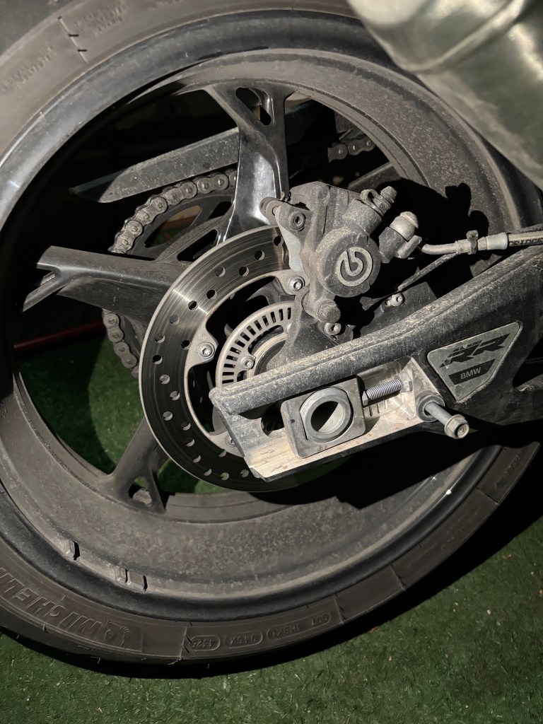
After many fruitful years of being driven around by a driver, the Pope had a sudden urge to drive the popemobile a little, just to see if he still remembers how to drive. So he asked his driver – Do you mind if I’ll drive back home today? The driver thought a bit and then agreed. The Pope and his driver switched places. The Pope was happy to see that he still drives very well. They approached the gates of the Vatican and the Swiss Guard at the entrance waved them to stop. Suddenly the Swiss Guard fainted and fell. The other guard waved the popemobile in and woke up his friend. – What happened to you? – You won’t believe who just came in, said the still dazed guard – Who came in? – I don’t know, but the Pope is his driver!
I remembered this joke when I realized that on my S-1000 RR, the rear brake is a Brembo!
הבדיקה השישית היתה קצרה, יחסית מהירה, כואבת ובעיקר מיותרת. זו היתה בדיקת דם נוספת, חזרה על חלק מהבדיקות בפגישה הרביעית. הכל היה בסדר בבדיקה הרביעית, אבל קרה משהו לאחת ממבחנות הדם. נדמה לי שהמדבקה עם הפרטים שלי התנתקה מהמבחנה. הייתי יכול לשאול מה בדיוק קרה, אבל האחות שהתקשרה אלי היתה נבוכה גם בלי חקירה צולבת אז התאפקתי
הגעתי היום בשעות הבוקר המאוחרות מאוד לבית הרפואה. התקבלתי בחיוכים ופירגון גורף כיאה למעמדי, ונשלחתי אל האחיות
האחות האחראית הביאה מדבקות חדשות והזמינה רופא. הרופא חייב להיות נוכח, מפני שזו בדיקת דם לסוג, וטעות בסוג הדם קטלנית יותר מכל סוג אחר של טעות. לכן רופא מטפל במבחנה, מוודא שהדם שייך לי ואני הוא עצמי – אני צריך למסור לו את תעודת הזהות שלי ולאמר את מספר הזהות
למרבה הצער, בגלל חשיבות הבדיקה צריך לחזור עליה פעמיים. כלומר, אני צריך להדקר עוד לפחות פעם אחת עוד בשלב ההכנות. והאמת חייבת להאמר, קצת מתחיל להמאס לי מבדיקות דם. כל דקירה בפני עצמה לא כל כך כואבת, אבל עכשיו אני יודע כבר למה לצפות ומשום מה זה מציק יותר. גם הרגישות באיזור הדקירה נשארת לזמן ארוך יותר. ובבדיקה החמישית נתקלתי כבר במחט של 10 סנטימטרים כמו שאספר בפוסט הרלוונטי. הרופא שהכניס לי את העירוי הסביר בחיוך שנגמרו לו המחטים הרגילות ולכן הוא משתמש במחטים לפילים. האמת, האמנתי לו
בקיצור, לא היה נעים. אבל לפחות היה די מהיר.
היידענע שלי, התנינה, טוענת שאני פוחד ממחטים. תמיד חשבתי שהיא טועה, אבל אני מתחיל לחשוב שאולי היא צודקת, וכמו בהרבה תחומים מכירה אותי טוב יותר מאשר אני מכיר את עצמי